
Antenna arrangement

a technology of fantennas and antennas, applied in the direction of resonant antennas, antenna earthings, radiating elements structural forms, etc., can solve the problems of limited antenna frequency characteristics and unsatisfactory increase in overall antenna siz

Inactive Publication Date: 2010-01-21
SONY ERICSSON MOBILE COMM AB
View PDF12 Cites 30 Cited by
  • Summary
  • Abstract
  • Description
  • Claims
  • Application Information

AI Technical Summary

Benefits of technology

[0010]Embodiments of the present invention provide a PIFA device and a method for controlling the PIFA device that can satisfy the characteristics of various frequencies in a multi-frequency environment in a mobile communication terminal, without compromising performance in terms of high signal transmission strength, good reception of weak signals, and the limited dimensions.

Problems solved by technology

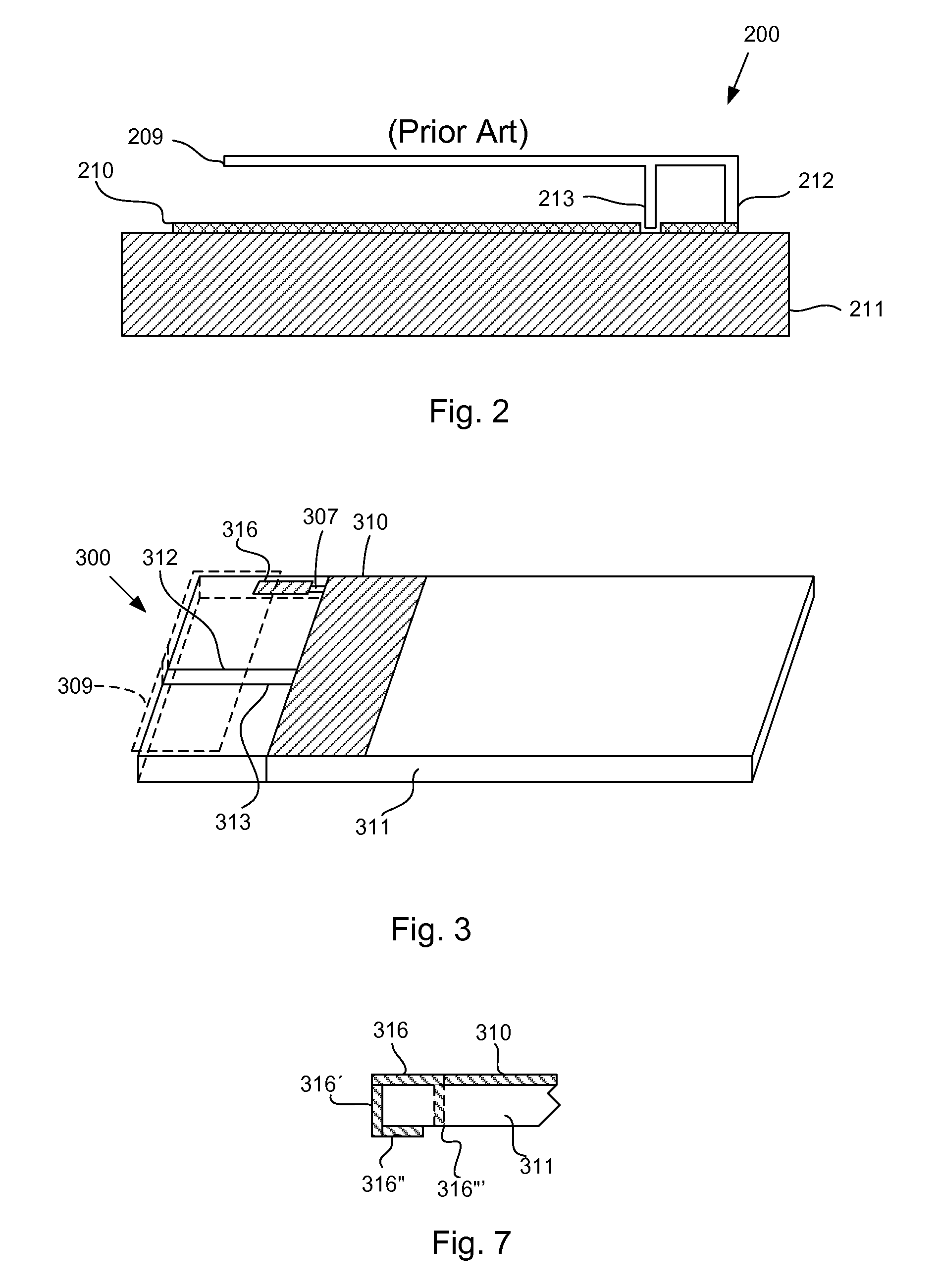
To change the bandwidth of PIFA 200, the height must be increased which will lead to an undesirable increase in the overall antenna size.
However, as the PIFA is limited by the space within the mobile communication terminal this results in limited antenna frequency characteristics and therefore the usual PIFA is designed to maximize the frequency for only one of the frequency bandwidths required.

Method used


Image

  • Antenna arrangement
  • Antenna arrangement
  • Antenna arrangement

Examples


Embodiment Construction

[0023]Exemplary antenna designs described in the following description may be “planar” antennae. A “planar” antenna may have an extended shape that lies generally along a plane, i.e., the antenna may have three dimensions but one of the dimensions may be an order of a magnitude less than the other two dimensions.

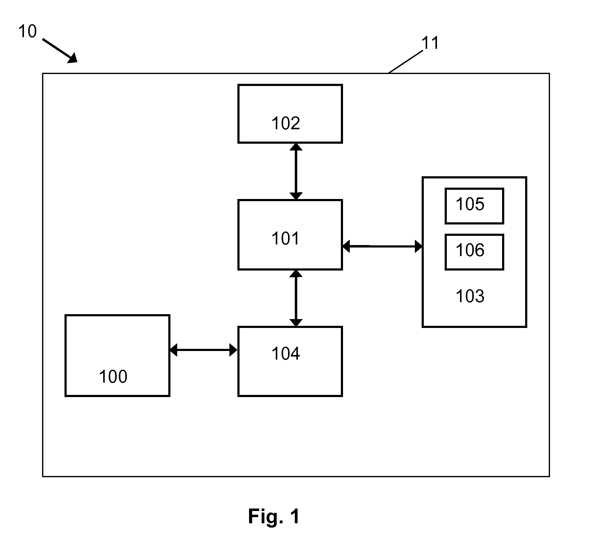
[0024]FIG. 1 illustrates a block diagram of an exemplary wireless communication device 10. Wireless communication device 10 may include a housing 11, a controller 101, a memory 102, a user interface 103, a transceiver 104, a key input unit 105, a display unit 106, and a multiband antenna 100. Transceiver 104 may interface wireless communication device 10 with a wireless network using antenna 100. It is appreciated that transceiver 104 may transmit or receive signals according to one or more of any known wireless communication standards known to the person skilled in the art. Controller 101 may control the operation of wireless communication device 10 responsive to programs s...


PUM


Abstract

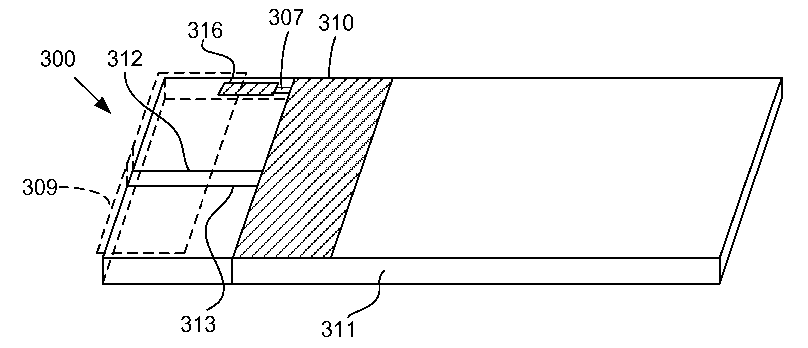
An antenna arrangement may include: a ground plane, a feed element, and a radiating element coupled to the feed element, the radiating element being substantially parallel to and vertically displaced from the ground plane by the feed element and a shortening element. The antenna may also include a conductive portion coupled to the ground plane using a switching element, the conductive portion being configured to alter the size of the ground plane.

Description

TECHNICAL FIELD[0001]The present invention generally relates to antennas and, more particularly, to a semi-planar inverted F-antenna (PIFA) including a switching technology that may switch between, for example, GSM 850 and GSM 900, without affecting the High Band frequencies.BACKGROUND OF THE INVENTION[0002]Wireless communication equipment, such as cellular and other wireless telephones, wireless network (WiLAN) components, GPS receivers, mobile radios, pagers, etc., use multi-band antennas to transmit and receive wireless signals in multiple wireless communication frequency bands. Consequently, one of the critical components of wireless devices is the antenna which should meet the demands of high performance in terms of high signal transmission strength, good reception of weak signals, increased (or narrowed, if required) bandwidth, and small dimensions.[0003]Planar inverted F-antennas (PIFAs) have many advantages. They are easily fabricated, have a simple design, and cost little t...

Claims


Application Information

Patent Timeline
Patent Type & Authority Applications(United States)
IPC IPC(8): H01Q1/48H01Q1/38
CPCH01Q1/243H01Q9/0442H01Q9/0421H01Q1/48H01Q1/24H01Q9/04H01Q5/00
Inventor AZHARI, ALEXANDER
Owner SONY ERICSSON MOBILE COMM AB
Learn More