Wireless communication system, wireless terminal station, wireless base station, and wireless communication method

a wireless communication and wireless terminal technology, applied in the field of wireless communication systems, can solve the problems of limited communication areas, limited use and application environments, and need for adjustment of directivity, and achieve the effect of efficient use of a band

Active Publication Date: 2010-01-21
MITSUBISHI ELECTRIC CORP
View PDF4 Cites 139 Cited by
  • Summary
  • Abstract
  • Description
  • Claims
  • Application Information

AI Technical Summary

Benefits of technology

[0021]According to the present invention, the wireless communication terminal stations covered by the same base station exchange information concerning directional beams and, in direct communication, share the information of directional beams each other. Therefore, there is an effect that it is possible to realize direct communication using the directional beams. There is also an effect that it is possible to efficiently use a band compared with communication performed via the base station.

Problems solved by technology

Therefore, communication areas are limited and environments of use and applications are limited.
On the other hand, after the wireless apparatus is set, it is likely that adjustment of directivity is necessary because of a change in environment or the like.

Method used


Image

  • Wireless communication system, wireless terminal station, wireless base station, and wireless communication method
  • Wireless communication system, wireless terminal station, wireless base station, and wireless communication method
  • Wireless communication system, wireless terminal station, wireless base station, and wireless communication method

Examples


first embodiment

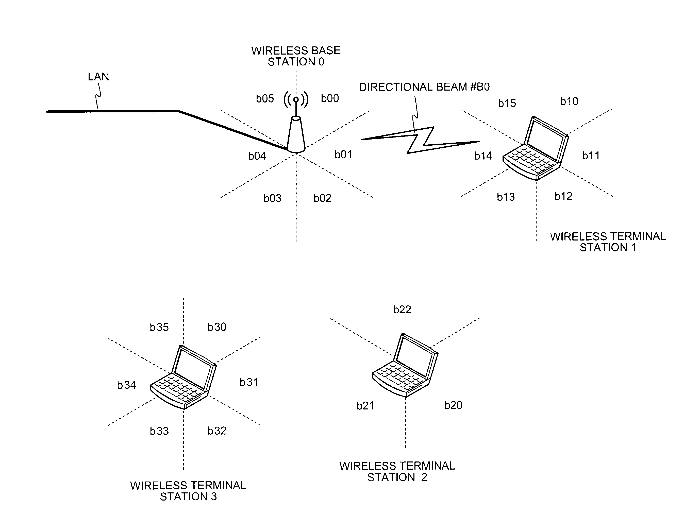
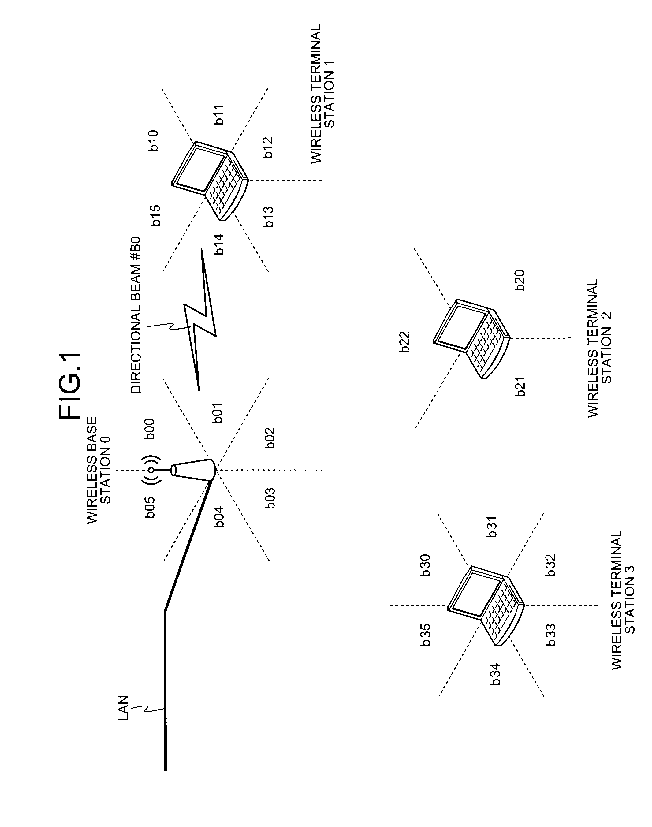
[0099]FIG. 1 is a diagram of a configuration example of a first embodiment of a wireless communication system according to the present invention. This wireless communication system includes a wireless base station (which may also be referred to as PNC or AP) 0 connected to, for example, a LAN as a wired network and a plurality of wireless terminal stations (which may also be referred to as DEV or STA) 1, 2, and 3 set in a service area of the wireless base station 0. In FIG. 1, areas divided by dotted lines arranged around the wireless base station 0 indicate directions of directional beams set for convenience in this embodiment. This indicates that, when the wireless base station 0 transmits data or the like in the respective directions, the wireless base station 0 can transmit the data or the like using directional beams formed in desired directions by setting directional beams of beam numbers (b00, b01, . . . , and b05) shown in the areas. The same applies to dotted lines arranged...

second embodiment

[0174]A second embodiment is explained. In this embodiment, operation for efficiently transmitting a DD frame compared with the first embodiment and performing device discovery is explained. A precondition (a configuration of a wireless communication system) and a basic sequence are the same as those shown in FIGS. 14 and 15 explained in the first embodiment. Therefore, only differences are explained in this embodiment.

[0175]First, operation until the wireless base station 0 performs “Device Discovery start notification” to the wireless terminal station 1 shown in FIG. 15 is the same as that in the first embodiment. Operation from the “Device Discovery start notification” is explained.

[0176]The wireless base station 0 transmits “Device Discovery start notification” including start and end times (a DD period) of device discovery, directional beam switching timing, and an access method to the wireless terminal station 1 and the wireless terminal station 2 using announcement informatio...

third embodiment

[0182]Subsequently, a third embodiment is explained. In this embodiment, a highly-efficient discovery procedure is explained. A configuration of a wireless communication system is the same as that in the first embodiment (see FIG. 14) explained above.

[0183]FIG. 22 is a diagram of an example of a device discovery procedure in the third embodiment. A procedure until “Device Discovery start notification” is the same as that in the first embodiment. Therefore, explanation of this part of the procedure is omitted.

[0184]The wireless base station 0 transmits “Device Discovery start notification” including start and end times of device discovery (DD period), directional beam switching timing, an access method, and the like to the wireless terminal stations 1 and 2 using announcement information frame or an individual frame (Step S31). The other wireless terminal station 3 that receives this frame recognizes that the DD period has started and does not perform communication for a fixed time.

[...


PUM


Abstract

A first wireless terminal station transmits beam transmission direction identification information in all directions. A second wireless terminal station receives the transmission direction identification information, combines reception direction identification information and the transmission direction identification information, and transmits directivity direction combination information to a wireless base station. The first and the second wireless terminal stations form directional beams in directions indicated by the directivity direction combination information to thereby perform a direct communication.

Description

TECHNICAL FIELD[0001]The present invention relates to a wireless communication system that performs communication using directional beams, and, more particularly to a wireless communication terminal station that has a function of specifying a combination of directional beams that wireless terminal stations covered by a common wireless base station use when the wireless terminal stations perform direct communication.BACKGROUND ART[0002]Most of antennas used in conventional wireless LAN (Local Area Network) systems and Ultra-wideband (UWB) wireless systems depend on characteristics of frequency bands used in the systems and have directivity of relatively wide angles. Therefore, applications that can be used in and environments that can be applied to the systems are varied and expected to continue to spread in future. However, there is an increasing demand for an increase in transmission speed of wireless communication in recent years. Wireless communication systems that use a millimet...

Claims


Application Information

Patent Timeline
Patent Type & Authority Applications(United States)
IPC IPC(8): H04W40/00
CPCH04B7/0617H04B7/0619H04B7/0695H04W8/005H04W72/0426H04W72/046H04W76/023H04W28/065H04W76/14H04W72/27
Inventor NAGAI, YUKIMASAYAMAUCHI, TAKAHISAKOSAKA, TETSUYA
Owner MITSUBISHI ELECTRIC CORP
Why Eureka
Try Eureka