Method of measuring in situ differential emissivity and temperature

a technology of differential emissivity and temperature measurement, applied in the field of methods, can solve problems such as failure of various components, further deterioration or spalling of coatings, and weakening of superalloy bodies

Inactive Publication Date: 2010-01-21
SIEMENS ENERGY INC
View PDF49 Cites 17 Cited by
  • Summary
  • Abstract
  • Description
  • Claims
  • Application Information

AI Technical Summary

Benefits of technology

[0010]The present invention provides a method of measuring the in situ emissive properties of two sites on a body. The sites may, or may not, be in substantial proximity to one another. Another aspect of the present invention is a method of measuring the temperature of a site on a body, where the method relies on the in situ emissive properties of the site being measured. The method of the present invention also measures the temperature of a site on a body in a manner that minimizes errors caused by reflected ambient radiation. Yet another aspect of the present invention is a method of measuring the temperature of a portion of, or all of, a body without the need to conduct an excessive number of measurements.
[0015]Although useful for measuring the temperature of a site on any body, the methods of the present invention may be particularly useful for measuring the temperature of a site when the site is not a black body emitter, the site is located in a highly reflected environment, there is a significant intensity of ambient radiation impinging on the site, or any combination of these factors. Since the method of the preset invention eliminates, or greatly reduces, error caused by a highly reflected environment and deviations from the black body emitter assumption, the method is ideal for measuring sites on bodies including, but not limited to, components of turbine engines, furnaces, boilers, and similar bodies.

Problems solved by technology

These high temperatures can cause failure of various components unless the components are protected from the heat.
When spalling or deterioration occurs, stress in the immediate area causes the surface to heat up resulting in further deterioration or spalling of the coating and, eventually, weakening of the superalloy body.
Determining the temperature of a turbine component using radiation detected from a site on a body located within the turbine is complicated by the fact that emissivity is difficult to determine.
Both the black body assumption and the laboratory estimate often result in inaccuracies because emissivity is a function of temperature, surface type, surface age, and other factors.
Similarly, if the emissivity cannot be determined or eliminated from the calculation, an error may be introduced into the temperature measurement.
Another source of error introduced by the black body assumption or emissivity estimates stems from the amount of infrared radiation emitted from the site.
Thus, a significant error in the temperature measurement may result if the black body assumption is used and the emissivity deviates significantly from this assumption.
Similarly, the emissivity estimates can be incorrect if the age or condition of the actual surface cause it to have an emissivity that is significantly different from the sample material that is tested.
A major disadvantage of this method is that the measurements are made on a single site on the turbine component.
Furthermore, the '575 method does not disclose a method for measuring the temperature of a site based on in situ measurements of the site's emissive properties.

Method used


Image

  • Method of measuring in situ differential emissivity and temperature
  • Method of measuring in situ differential emissivity and temperature
  • Method of measuring in situ differential emissivity and temperature

Examples


example # 1

Example #1

[0045]One method of determining the differential emissivity between the first site and the second site is disclosed below. Each of the detection steps described in the specification will yield a total intensity of radiation at a first specified wavelength, ixy(λ1). The equation for the total intensity detected will have the following general form:

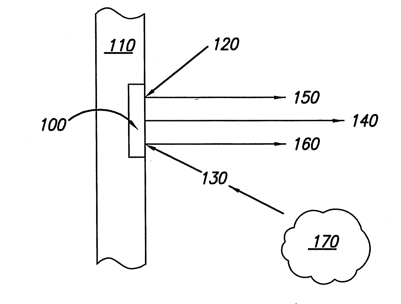
ixy(λ1)=[ambient radiation having wavelength λ1 that is reflected by site x]+[external radiation having wavelength λ1 that is reflected by site x]+[radiation emitted by site x having wavelength λ1]

The radiation detected from site X arising at a first wavelength, λ1, with and without radiation irradiated at λ1 are represented below:

iXE(λ1)=rx+ex+ix(εx, λ1, T) (with reflected external radiation)

ix0(λ1)=rx+0+ix(εx, λ1, T) (with no reflected external radiation)

where:[0046]rx=ambient radiation having wavelength λ1 that is reflected by site X;[0047]ex=external radiation irradiated having wavelength λ1 that is reflected by site X;[0048]i...

example # 2

Example #2

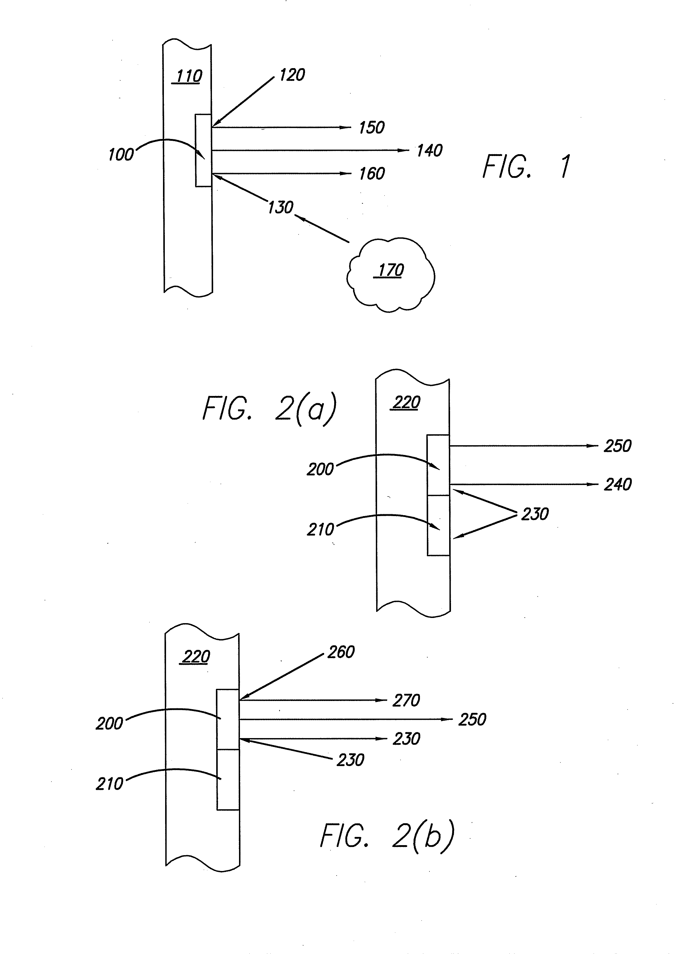
[0056]One method of determining the temperature of the first site and the second site is disclosed below. Taking each of the detection steps described in an embodiment for measuring temperature described above will yield a total intensity of radiation at a specified wavelength, ixy(λ1). In one method a total of six intensity measurements are taken using infrared radiation detection devices. For each site, the total intensity of radiation at a first wavelength will be detected with and without an external source of radiation, R(λ1). For each site, the total intensity of radiation at a second wavelength, λ2, will be detected without an external source of radiation. Using the labeling paradigm described in Example #1, the detected radiation arising from sites one and two can be represented as follows:

i1E(λ1)=r1+e1+i1(ε1, λ1, T)   (17)

i10(λ1)=r1+0+i1(ε1, λ1, T)   (18)

iE2(λ1)=r2+e2+i2(ε2, λ1, T)   (19)

i20(λ1)=r2+0+i2(ε2, λ1, T)   (20)

i10(λ2)=r1+0+i1(ε1, λ2, T)   (21)

i20(λ2)=r2+...

example # 3

Example #3

[0064]Another method of determining the temperature of the first site and the second site is a slight modification of Example #2. As in Example #2, the method includes a total of six intensity measurements. For each site, the total intensity of radiation at a first wavelength may be detected with and without an external source of radiation, R(λ1). For each site, the total intensity of radiation at a second wavelength, λ2, will be detected with an external source of radiation, R(λ2). Using the labeling paradigm described in Example #1, the intensity of detected radiation arising from sites one and two can be represented as follows:

i1E(λ1)=r1+e1+i1(ε1, λ1, T)   (33)

i10(λ1)=r1+0+i1(ε1, λ1, T)   (34)

i2E(λ1)=r2+e2+i2(ε2, λ1, T)   (35)

i20(λ1)=r2+0+i2(ε2, λ1, T)   (36)

i1E(λ2)=r1+e1+i1(ε1, λ2, T)   (37)

i2E(λ2)=r2+e2+i2(ε2, λ2, T)   (38)

[0065]As shown in Example #1, equations (33) through (36) can be combined to yield equation (16):

Δɛ=Δi0′(λ1)-ΔiE(λ1)Eo

[0066]Sites one and two may b...


PUM

PropertyMeasurementUnit
temperatureaaaaaaaaaa
emissivityaaaaaaaaaa

Abstract

A method for measuring the differential emissivity between two sites on the surface of a body and the temperature of the two sites. The method includes a plurality of measurements of the infrared radiation arising from each of the two sites under a number of different conditions. Some of the measurements include irradiation by external infrared radiation at a known wavelength and intensity. The infrared radiation arising from each of the sites may include emitted radiation, reflected ambient radiation, and reflected external radiation. Additionally, the temperature determined using the method described can be used to calibrate infrared imaging devices used to inspect the entire body.

Description

CROSS-REFERENCE TO RELATED APPLICATION[0001]This application is a continuation of U.S. patent application Ser. No. 11 / 217,884 filed on Sep. 1, 2005.FIELD OF THE INVENTION[0002]The present invention is directed generally to methods for on-line monitoring of components and, in particular, making measurements of temperature and differential emissivity.BACKGROUND OF THE INVENTION[0003]Combustion turbines typically operate at extremely high temperatures, for example, 1500° F. to 2000° F. for steam turbines and 2500° F. to 2900° F. for gas turbines. These high temperatures can cause failure of various components unless the components are protected from the heat. The components include the rotating blades of the turbine, and the vanes for directing gas flow within the turbine. A typical combustion turbine will have three to four rows each of blades and vanes, with approximately 50 to 100 blades or vanes per row, and will typically have approximately 500 total blades and vanes to protect. A...

Claims


Application Information

Patent Timeline
Patent Type & Authority Applications(United States)
IPC IPC(8): G01J5/00
CPCG01J5/0003G01J2005/0074G01J5/602G01J5/524G01J5/532
Inventor TWERDOCHLIB, MICHAEL
Owner SIEMENS ENERGY INC
Why Eureka
Try Eureka