
Image stitching and related method therefor

a technology of image stitching and image, applied in the field of image stitching, can solve the problem of not being able to capture the whole object of interest in a single field of view or a single imag

Active Publication Date: 2010-01-21
VAREX IMAGING CORP
View PDF21 Cites 104 Cited by
  • Summary
  • Abstract
  • Description
  • Claims
  • Application Information

AI Technical Summary

Benefits of technology

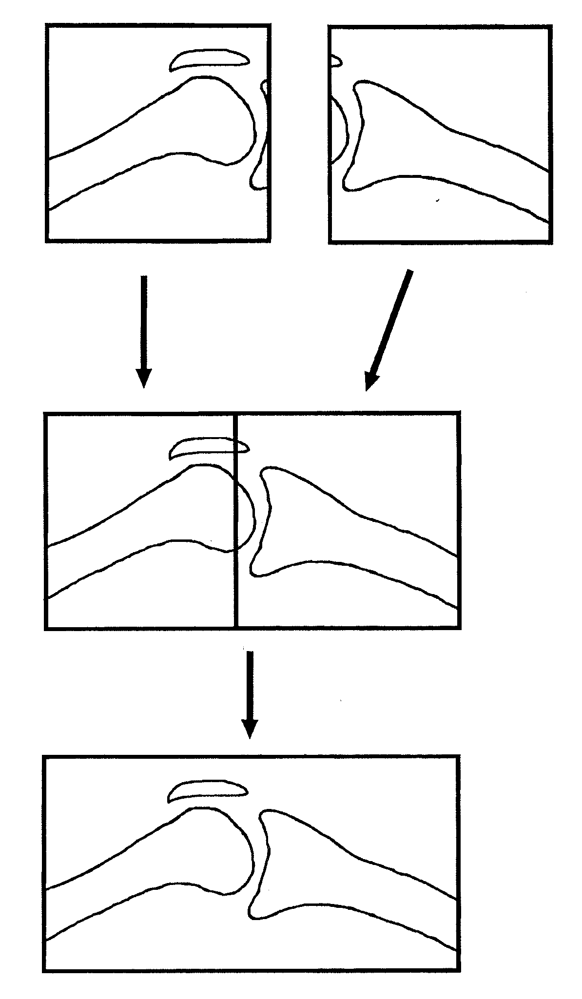
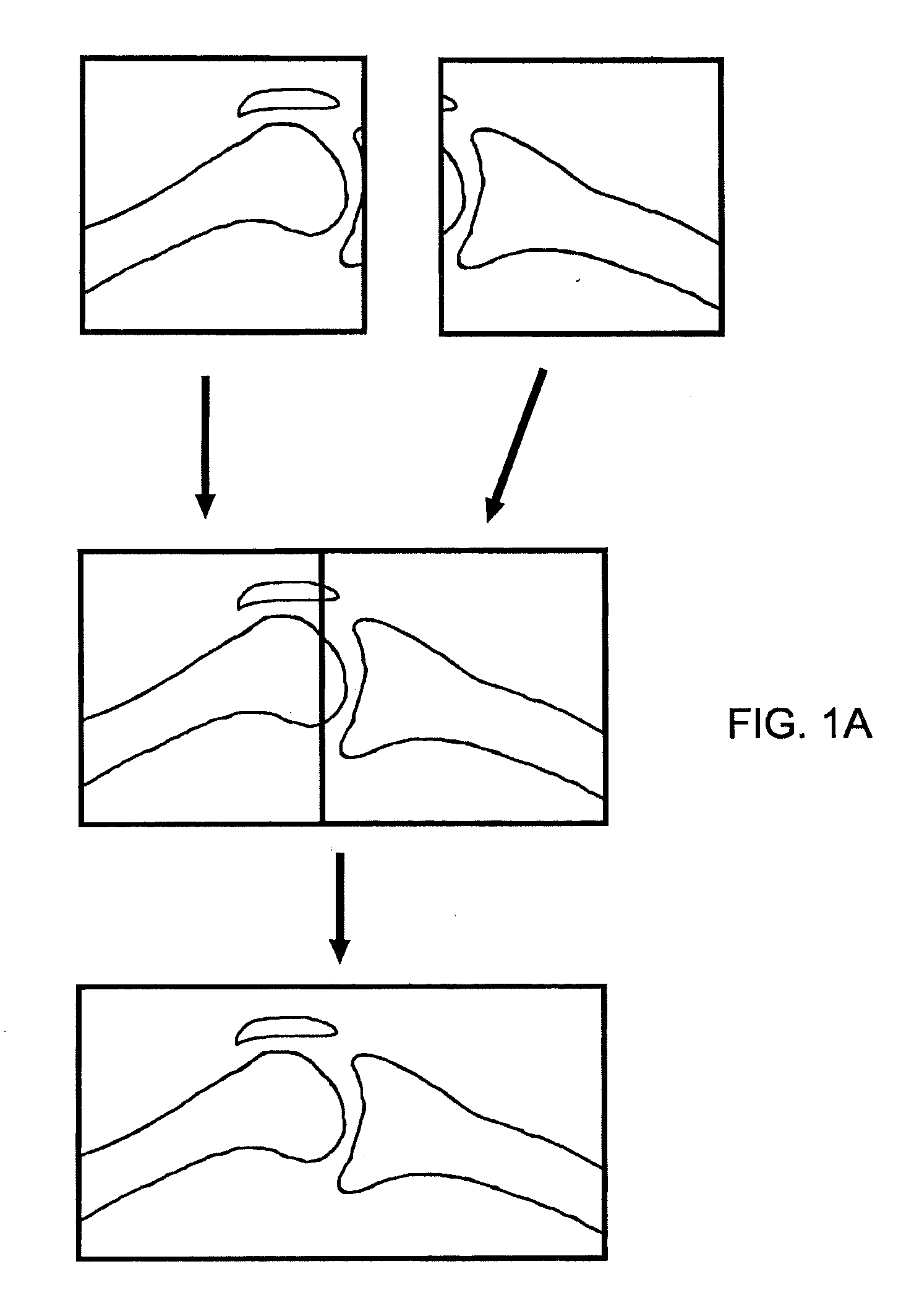
[0005]According to one aspect, a method to stitch images includes the steps of: providing a first digital image and a second digital image; reading the first digital image and the second digital image; determining a first Region of Interest (ROI) in the first digital image and a second ROI in the second digital image; determining a template window in the first digital image and a target window in the second digital image and a template in the template window; smoothing an image within the template and the target window; extracting selected features from within the template and the target window at a first resolution; matching the selected features of the template to features in the target window at a first resolution to make a first estimate of a stitching location; extracting selected features from within the template and target window at a second resolution higher than the first resolution; matching the selected features of the template to features in the target window at a second resolution to make a second estimate of the stitching location; performing a first evaluation of the second estimate of the stitching location; blending the second estimate of the stitching location; performing an evaluation of the stitching location; stitching the first digital image and a second digital image using the stitching location to create a stitched image; and saving the stitched image to memory.

Problems solved by technology

In many cases, such as in medical radiography applications, it might not be possible to capture the whole object of interest in a single field of view or a single image.

Method used


Image

  • Image stitching and related method therefor
  • Image stitching and related method therefor
  • Image stitching and related method therefor

Examples


Embodiment Construction

[0057]DEFINITIONS: Combining or “stitching” multiple images herein refers to substantially seamlessly joining two images having some finite overlap region. The words “fuse” or “fusing” are used synonymously to refer to the stitching process. Typically two images are joined at a time; more images can be joined by repeating the process.

[0058]A “template” is an area (region) defined within an image. In the context of image stitching, the template typically includes part or all of a region within an overlapping area of two images to be fused. As part of the image stitching method, a template selected from the first window, the “template window” is matched with a second window, the “target window”, by searching in the target window for the most similar image to the template. The template window and the target window typically include a common area or “overlap region” where the first and second images overlap each other.

[0059]A “mean projection of an image” is considered herein to be a su...


PUM


Abstract

A method to stitch images includes the steps of: determining a template window in the first digital image and a target window in the second digital image and extracting selected features from the selected windows and a template in the template window; extracting selected features from within the template at a first resolution; matching the selected features in the target window; extracting selected features from within the template and target window at a second resolution higher than the first resolution; matching the selected features in the target window; performing a first evaluation of the second estimate of the stitching location; blending the second estimate of the stitching location; performing an evaluation of the stitching location; stitching the first digital image and a second digital image using the stitching location to create a stitched image; and saving the stitched image to memory. A system to perform the method is also described.

Description

FIELD OF THE INVENTION[0001]This invention relates generally to a method for combining multiple overlapping images and more particularly to a method for image stitching.BACKGROUND OF THE INVENTION[0002]Images having low or high resolution are typically captured by use of a camera, Charge Coupled Device (CCD), IR camera, or Flat Panel Detector (FPD) with a visible, Infrared, or X-ray light source, respectively. In many cases, such as in medical radiography applications, it might not be possible to capture the whole object of interest in a single field of view or a single image. Therefore, multiple views of an area of interest are typically acquired as multiple images by automatically (synchronously) or manually (asynchronously) moving the sensor and light source with respect to the object of interest. Physical movement of the sensor and light source can be accomplished by horizontal movement only, vertical movement only, both horizontal and vertical movement, or rotational movement.[...

Claims


Application Information

Patent Timeline
Patent Type & Authority Applications(United States)
IPC IPC(8): G06K9/36
CPCG06T1/00G06T5/002G06T2207/30008G06T7/0028G06T2207/10116G06T5/20G06T7/33G06T5/70
Inventor KALAYEH, HOOSHMAND M.
Owner VAREX IMAGING CORP
Learn More