Sealed connector assembly

a connector and assembly technology, applied in the direction of coupling devices, coupling bases/cases, coupling devices, etc., can solve the problems of difficult maintenance, high cost of sealing of connector assemblies, failure of devices in which the connector assemblies are used, etc., and achieve the effect of reducing the space required

Inactive Publication Date: 2010-01-21
TE CONNECTIVITY CORP
View PDF25 Cites 19 Cited by
  • Summary
  • Abstract
  • Description
  • Claims
  • Application Information

AI Technical Summary

Benefits of technology

[0009]Another aspect of the invention is directed to a printed circuit board connector having a mating face and a circuit board mounting face. A connector receiving opening extends from the mating face and is dimensioned to receive a mating connector therein. Contacts extend from the connector receiving opening to beyond the circuit board mounting face, thereby allowing the printed circuit board connector to be mounted to a printed circuit board. Recessed areas are provided on either side of an elongated circuit board conta

Problems solved by technology

In these environments, the electrical connection between contacts can fail, causing the device in which the connector assemblies are used to also fail.
However, the sealing of these boxes can be expensive and can make for difficult maintenance issues.
To date, it has been difficult to provide such cable assemblies with the appropriate sealing to wi

Method used


Image

  • Sealed connector assembly
  • Sealed connector assembly
  • Sealed connector assembly

Examples


Embodiment Construction

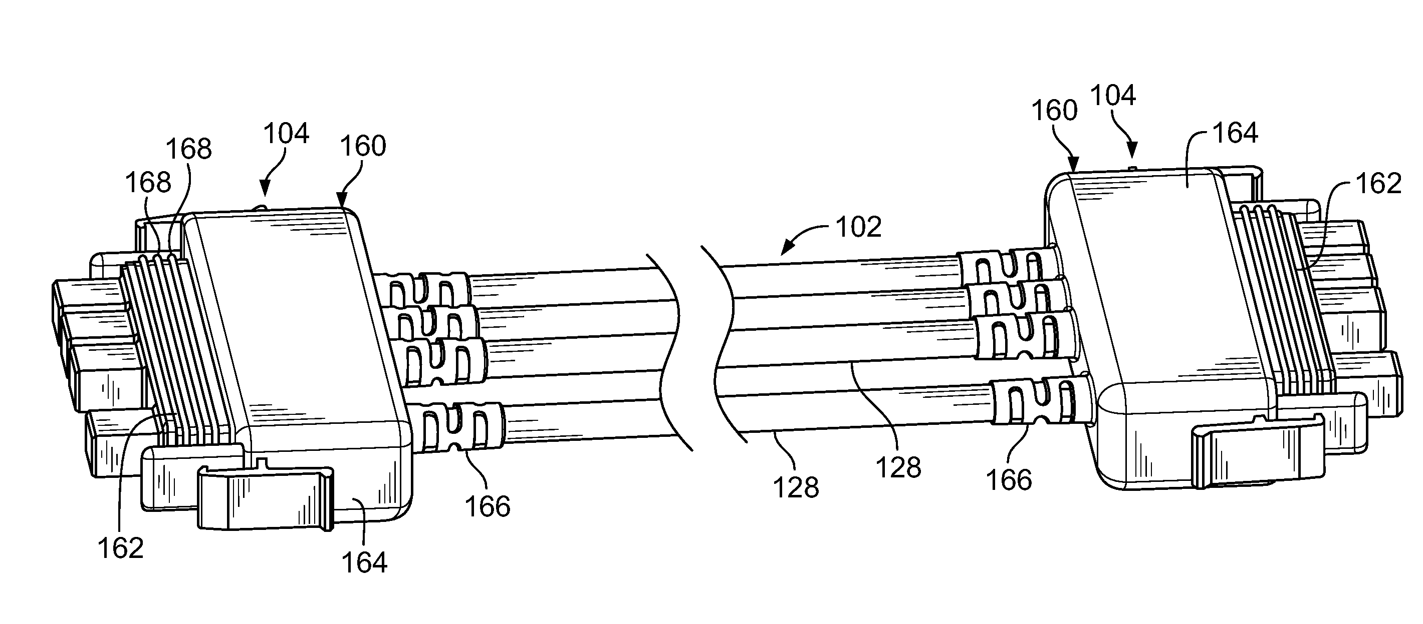
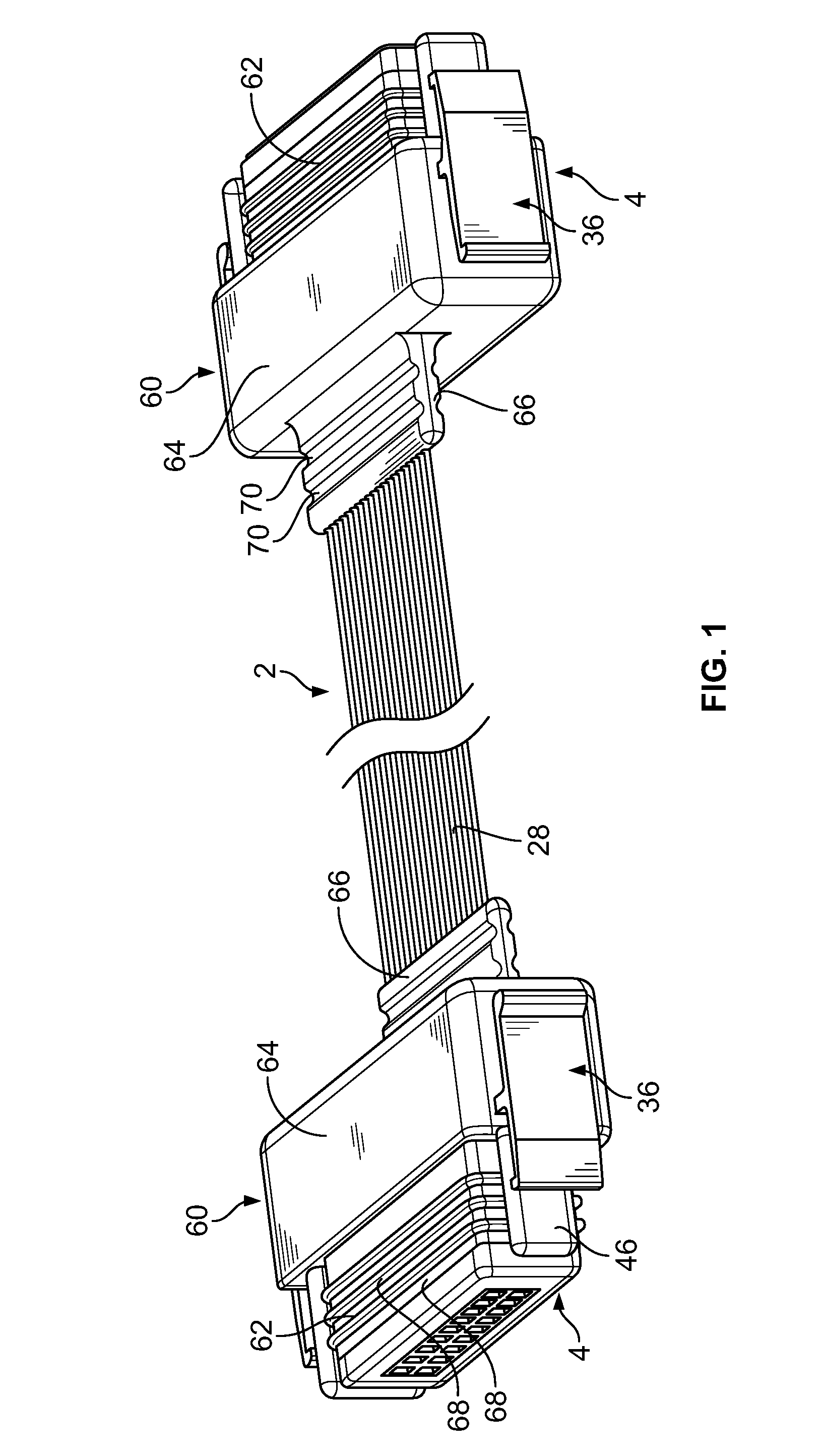
[0034]Referring to FIG. 1, a sealed ribbon cable assembly 2 is shown. The ribbon cable assembly 2 is manufactured to the desired length and has a sealed ribbon cable connector assembly 4 terminated thereto at either end.

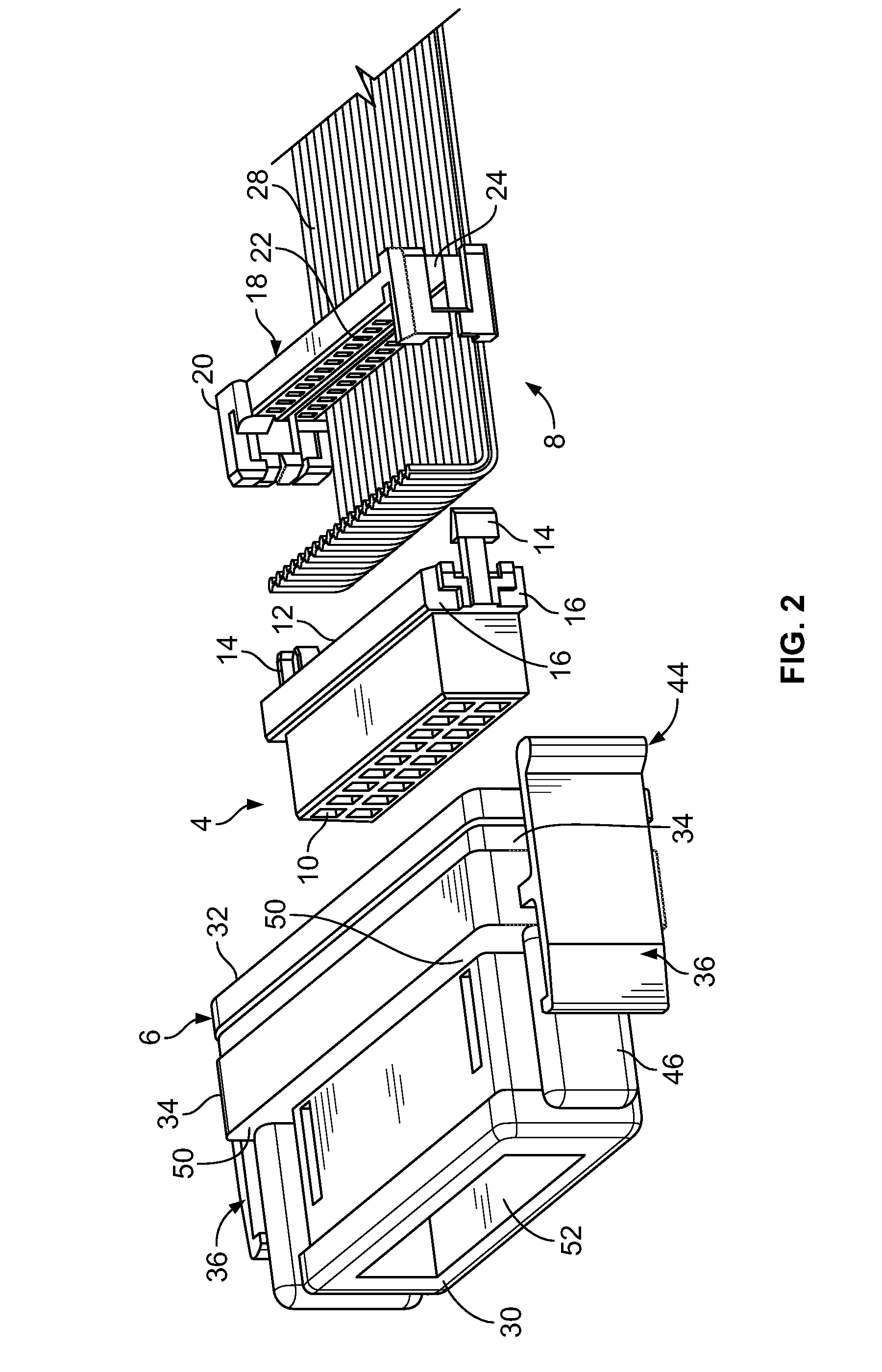
[0035]As best shown in FIG. 2, each ribbon cable connector assembly 4 has a molded housing 6 and a contact receiving housing 8. The contact receiving housing 8 has a header mating surface 10 and an oppositely facing ribbon cable mating surface 12. The ribbon cable mating surface 12 has insulation displacement contacts (not shown) extending therefrom in a direction away from the header mating surface 10. At either end of the ribbon cable mating surface 12, a locking latch 14 extends from the contact receiving housing 8 in a direction essentially perpendicular to the ribbon cable mating surface 12 and away from the header mating surface 10. Locking tabs 16 are positioned on either side of the base of each locking latch 14. A cover 18 is positioned proximate the ribbon ...


PUM


Abstract

A sealed connector system and components thereof is disclosed. The sealed connector system has a sealed cable assembly and a printed circuit board header assembly. The sealed cable assembly has a cable housing and a cable terminated thereto. A cover, as described above, is overmolded over a portion of the cable housing and a portion of the cable. The cover is one continuous member that acts as a seal to prevent contaminants from entering the cable housing. A printed circuit board header assembly is mated to the cable housing. The header assembly has recesses provided proximate a circuit board mounting surface, with the recesses being configured to provide additional space on a circuit board on which the header assembly is mounted. Legs or ribs may be provided proximate the ends of the circuit board contact area. The ribs provide stability to the printed circuit board connector and prevent the printed circuit board connector from being rotated relative to the printed circuit board. The sealed connector system may be provided with a cable housing ground shield proximate the header mating end of the cable housing and a header assembly ground shield may be provided in a cable housing receiving opening of the header assembly, whereby the cable housing ground shield and the header assembly ground shield are placed in electrical engagement with each other.

Description

FIELD OF THE INVENTION[0001]The invention relates to cable assemblies that can be used in harsh environments. In particular, the invention is directed to a sealed cable assembly and sealed connector system and components therefore.BACKGROUND OF THE INVENTION[0002]Electrical connector assemblies have long been used in environments that are harmful to the contacts. In these environments, the electrical connection between contacts can fail, causing the device in which the connector assemblies are used to also fail. In order to provide a more reliable electrical connection, seals have been applied to the connectors, to isolate the contacts from the harsh environments. These types of sealed connectors have proven beneficial in certain environments and with certain types of cable connectors.[0003]The use of power and / or signal connections in outdoor message centers and video scoreboards are applications in which the environment can effect the reliability of the electrical connection betwe...

Claims


Application Information

Patent Timeline
IPC IPC(8): H01R13/52H01R13/44
CPCH01R13/405H01R13/504H01R12/778H01R23/72H01R12/712H01R13/5845
Inventor DAILY, CHRISTOPHER GEORGEMOSTOLLER, MATTHEW E.
Owner TE CONNECTIVITY CORP
Why Eureka
Try Eureka