Antero-posterior placement of axis of rotation for a rotating platform

a technology of rotating platform and anterior placement, which is applied in the field of human body joint prosthesis, can solve the problems of deteriorating bones, articular cartilage and ligaments of the knee, reducing range of motion, and even pre-operative knee soft tissue used to cause movement such as flexion and extension in a healthy kn

Inactive Publication Date: 2010-01-21
DEPUY (IRELAND) LTD
View PDF53 Cites 73 Cited by
  • Summary
  • Abstract
  • Description
  • Claims
  • Application Information

AI Technical Summary

Problems solved by technology

Damage or disease can deteriorate the bones, articular cartilage and ligaments of the knee.
Such changes from the normal condition of the knee joint can ultimately affect the ability of the natural knee to function properly leading to pain and reduced range of motion.
Accordingly, the configuration of soft tissue used to cause movement such as flexion and extension in a healthy knee, or even a pre-operative knee, no longer achieves the same results when the knee is replaced with a prosthesis.
Additionally, the sacrifice of soft tissue results in reduced stability of the knee joint.
The resulting loss of joint stability can accelerate wear, cause a sensation of instability during certain activities of daily living, result in abnormal knee joint motion (kinematics), and / or result in a reduced dynamic moment arm to the quadriceps requiring increased force to control movement.
This sudden change in configuration, which is not believed to occur with a native knee, contributes to the sense of instability.

Method used


Image

  • Antero-posterior placement of axis of rotation for a rotating platform
  • Antero-posterior placement of axis of rotation for a rotating platform
  • Antero-posterior placement of axis of rotation for a rotating platform

Examples


Embodiment Construction

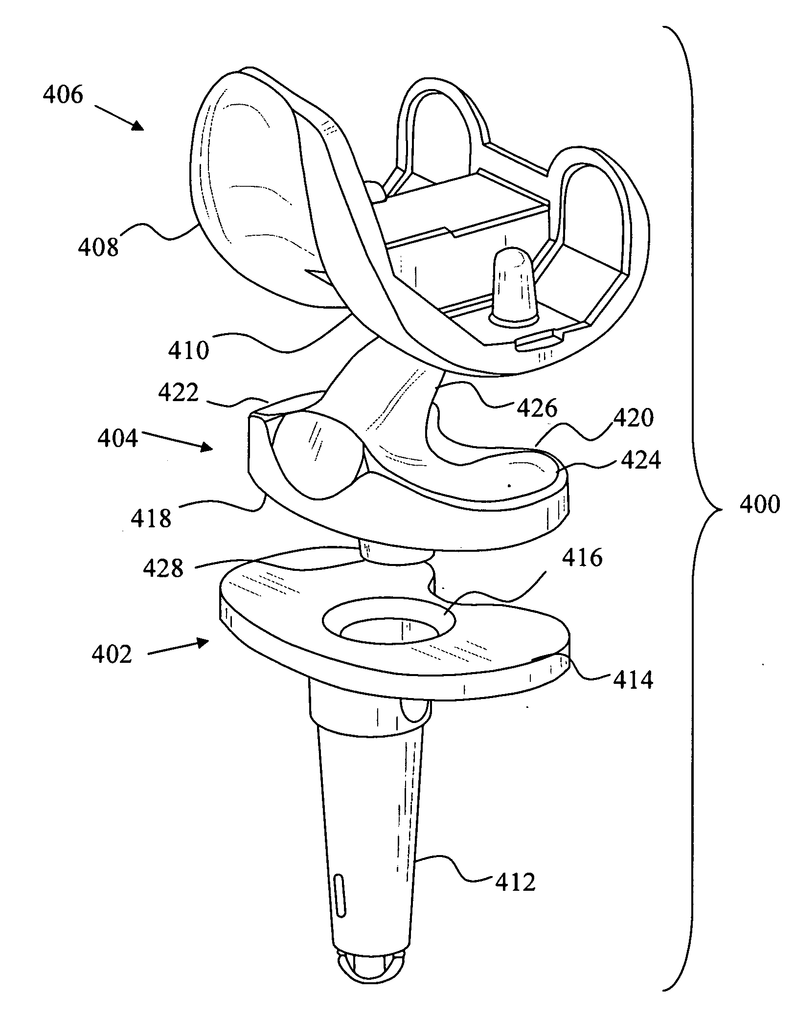
[0057]FIG. 5 depicts a knee replacement system 100 incorporating known features. The knee replacement system 100 includes a tibial tray 102, a tibial bearing insert 104 and a femoral component 106 having two femoral condyle elements 108 and 110. The tibial tray 102 includes an inferior stem 112 for attaching the tibial tray 102 to the tibia of a patient and a superior plateau 114 for receiving the tibial bearing insert 104. A coupling member 116 is located on the superior plateau 114.

[0058]The tibial bearing insert 104 includes an inferior tibial tray contacting surface 118 and a superior tibial bearing surface 120 The superior tibial bearing surface 120 includes a bearing surface 122 and a bearing surface 124 configured to articulate with the femoral condyle elements 108 and 110. A spine 126 extends upwardly from between the bearing surface 122 and the bearing surface 124. A coupling member 128 extends downwardly from the tibial tray contacting surface 118

[0059]The femoral componen...


PUM


Abstract

A knee replacement system includes a femoral component including a lateral condylar articulating portion and a medial condylar articulating portion, a tibial tray including an upper articulating surface, and a tibial insert including (i) a first articulating portion for articulating with the lateral condylar articulating portion with a first condylar dwell point, (ii) a second articulating portion for articulating with the medial condylar articulating portion with a second condylar dwell point, (iii) a lower articulating surface for articulating with the upper articulating surface, and (iv) a coupling member for coupling with the tibial tray and defining an axis of rotation about which the tibial insert rotates with respect to the tibial tray, the axis of rotation intersecting the upper articulating surface at a location posterior to a dwell axis including the condylar dwell points when the dwell axis is projected onto the upper articulating surface.

Description

[0001]Cross-reference is made to U.S. Utility patent application Ser. No. 12 / 165,579 entitled “Orthopaedic Femoral Component Having Controlled Condylar Curvature” by John L. Williams et al., which was filed on Jun. 30, 2008; to U.S. Utility patent application Ser. No. 12 / 165,574 entitled “Posterior Cruciate-Retaining Orthopaedic Knee Prosthesis Having Controlled Condylar Curvature” by Christel M. Wagner, which was filed on Jun. 30, 2008; to U.S. Utility patent application Ser. No. 12 / 165,575 entitled “Posterior Stabilized Orthopaedic Knee Prosthesis Having Controlled Condylar Curvature” by Joseph G. Wyss, which was filed on Jun. 30, 2008; to U.S. Utility patent application Ser. No. 12 / 165,582 entitled “Posterior Stabilized Orthopaedic Prosthesis” by Joseph G. Wyss, which was filed on Jun. 30, 2008; to U.S. Utility patent application Attorney No. 1671-0450 entitled “Knee Prostheses with Enhanced Kinematics” by Joseph G. Wyss, et al., which was filed on Jul. 16, 2008; and to U.S. Prov...

Claims


Application Information

Patent Timeline
Patent Type & Authority Applications(United States)
IPC IPC(8): A61F2/38
CPCA61F2/3868
Inventor WILLIAMS, JOHN L.GOMAA, SAID T.WYSS, JOSEPH G.
Owner DEPUY (IRELAND) LTD
Why Eureka
Try Eureka