Vacuum Cleaner

Active Publication Date: 2010-01-28
AB ELECTROLUX
View PDF99 Cites 9 Cited by
  • Summary
  • Abstract
  • Description
  • Claims
  • Application Information

AI Technical Summary

Benefits of technology

[0007]The invention is thus based on the understanding that the above-mentioned object can be achieved by a stick formed vacuum cleaner, wherein at least one friction increasing and slip reducing layer is provided on at least an upper portion of the rear side of the stick formed support body. With a vacuum cleaner formed in this way it is possible to temporarily set it aside quickly and easily without the risk for the vacuum cleaner to fall to the floor by sliding or tipping with the possible risk for the vacuum cleaner to get damaged or that it will cause damage to furnishings. In this way the operator also do not need to bend down to place the vacuum cleaner on the floor or to pick it up.
[0008]Within this general idea, the invention may be carried out in many different ways. In a most preferred embodiment, the vacuum cleaner is provided with an elongated strip of a slip reducing material attached to an upper portion of a rear side of the support body. However, in most cases it is preferred that the slip reducing material is not positioned on the rear side of a handle part, since it can feel somewhat unpleasant to grip around the strip of a high friction material. This maybe also can give a little too good grip for the hands, while it is desirable to allow some sliding between the hands and the handle during moving of the vacuum cleaner. In a preferred embodiment, the handle part is formed as a short portion in the upper part of the support body which is slightly angled in relation to the rest of the support body, and the slip reducing strip is attached from the handle portion and a distance downwards. By making the strip somewhat elongated, the advantage is obtained that the vacuum cleaner may be leaned towards an object, for example a table top, in different desirable angles, or towards objects having different heights, while the slip reducing strip still engages the object.
[0009]To also allow leaning of the vacuum cleaner towards a vertical surface, e.g. a wall,

Problems solved by technology

However, in most cases it is preferred that the slip reducing material is not positioned on the rear side o

Method used


Image

  • Vacuum Cleaner
  • Vacuum Cleaner
  • Vacuum Cleaner

Examples


Example

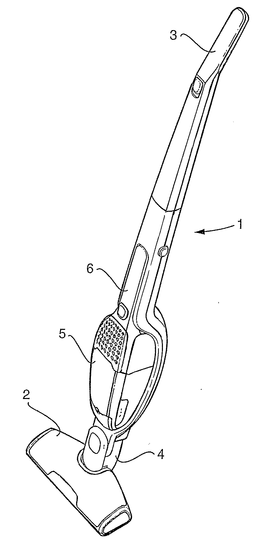
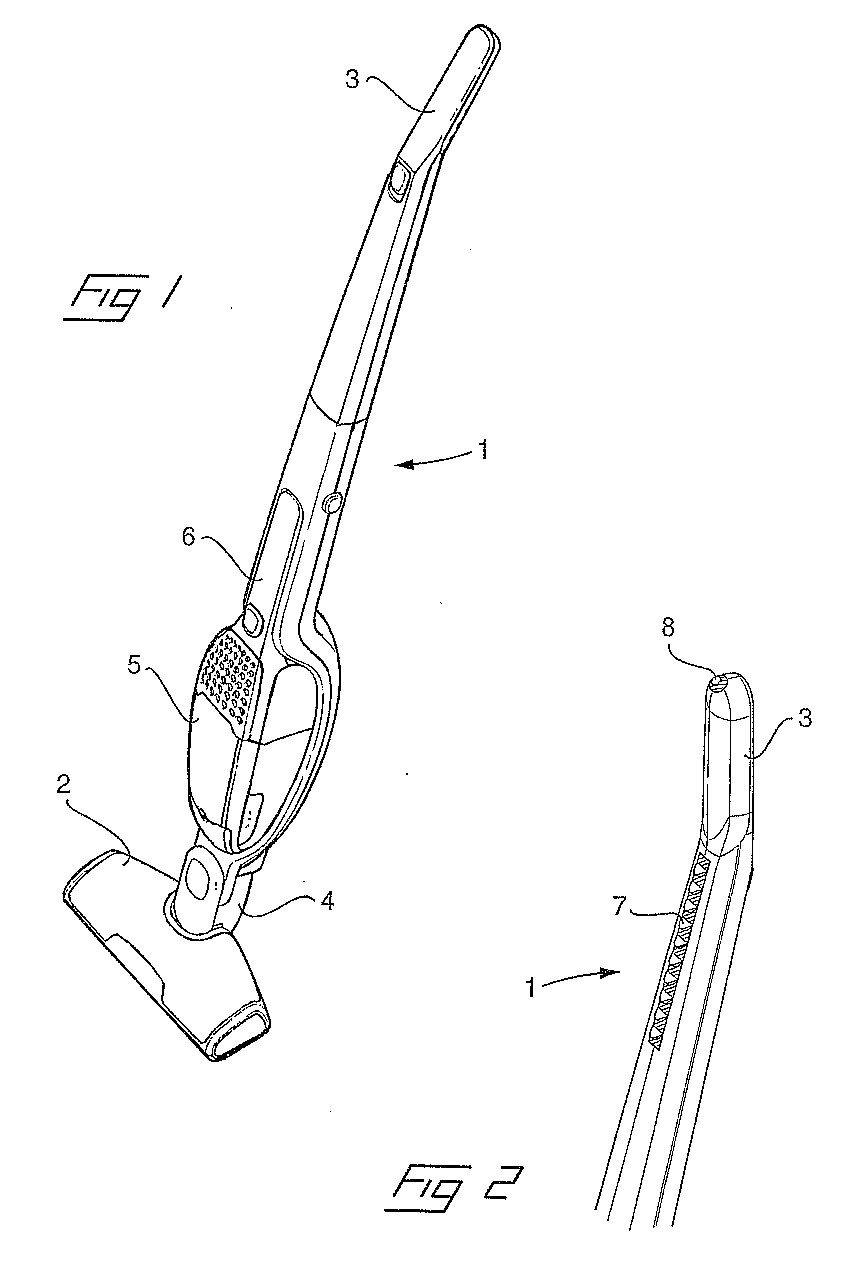
[0020]Reference is first made to FIG. 1 in which is illustrated a vacuum cleaner of the general kind being intended for the present invention. The vacuum cleaner comprises an elongated, stick formed support body 1 having a nozzle device 2 in its lower end and a handle part 3 in its upper end. The nozzle device 2 is connected to the support body by means of a joint 4 such that the nozzle device is pivotable in a plane in parallel as well as a plane perpendicular to the support body. As seen from the drawings, the handle part 3 is angled in relation to the support body 1.

[0021]The illustrated vacuum cleaner is of the kind having a separate vacuum unit 5, which in the drawings is shown mounted in a mounting recess in the support body, but which also is detachable to be used as a handheld vacuum cleaner. For this reason the vacuum unit 5 comprises an electric motor, a fan, a debris collecting compartment, a handle 6 in its upper end and an integrated nozzle in its lower end. In the moun...


PUM


Abstract

The invention relates to a vacuum cleaner of a type comprising an elongated support body (1) including a handle (3) in an upper end of the support body, a nozzle device attached to a lower end of the support body by means of a rotatable joint, and a vacuum unit, including an electric motor, a fan and a debris collecting compartment, being accommodated in the support body. An upper portion of the support body (1) is provided with a layer (7, 8) of a slip reducing material at least on a rear surface thereof.

Description

[0001]The invention relates to a vacuum cleaner of a type comprising an elongated support body including a handle in an upper end of the support body, a nozzle device attached to a lower end of the support body by means of a rotatable joint, and a vacuum unit, including an electric motor, a fan and a debris collecting compartment, being accommodated in the support body.BACKGROUND OF THE INVENTION[0002]Vacuum cleaners of the above specified kind have become common on the market during recent years. They possess an advantage in relation to conventional vacuum cleaners by the fact that the entire vacuum cleaner is assembled into one single unit instead of a separate vacuum unit, which during work will be dragged over the floor, and a separate hose and tube provided with a nozzle device in the end. The design of a vacuum cleaner according to the preamble is more compact which will facilitate the cleaning work.[0003]Many of these vacuum cleaners are provided with a vacuum unit, which is ...

Claims


Application Information

Patent Timeline
IPC IPC(8): A47L5/00
CPCA47L5/225A47L9/325A47L9/0009A47L5/28
Inventor BESKOW, JONASMIEFALK, HAKANFJELLMAN, OSKARGREN, CHRISTIANSVANTESSON, ESBJORN
Owner AB ELECTROLUX
Why Eureka
Try Eureka