
Filter, duplexer and communication apparatus

a technology of communication apparatus and duplexer, which is applied in the manufacture of stator/rotor bodies, manufacturing tools, press rams, etc., to achieve the effect of convenient assembly of stators

Inactive Publication Date: 2010-01-28
HONDA MOTOR CO LTD
View PDF5 Cites 11 Cited by
  • Summary
  • Abstract
  • Description
  • Claims
  • Application Information

AI Technical Summary

Benefits of technology

[0012]A major object of the present invention is to provide a stator manufacturing apparatus, which can increase the space factor of windings.
[0027]The stator manufacturing apparatus preferably includes a spacer moving means for moving the spacer holding jig vertically downward. The spacers provide clearances between the adjacent coils when the stator is assembled. After the coils have been compressed radially, the spacer moving means moves the spacer holding jig vertically downward so as to release the spacers from between the adjacent separate cores. Clearances between the adjacent coils thus are maintained, thereby preventing the adjacent coils from becoming short-circuited.

Problems solved by technology

However, Japanese Laid-Open Patent Publication No. 11-341748 discloses nothing concerning structural apparatus details for carrying out the above method.

Method used


Image

  • Filter, duplexer and communication apparatus
  • Filter, duplexer and communication apparatus
  • Filter, duplexer and communication apparatus

Examples


Embodiment Construction

[0043]A stator manufacturing apparatus according to a preferred embodiment of the present invention will be described in detail below with reference to the accompanying drawings.

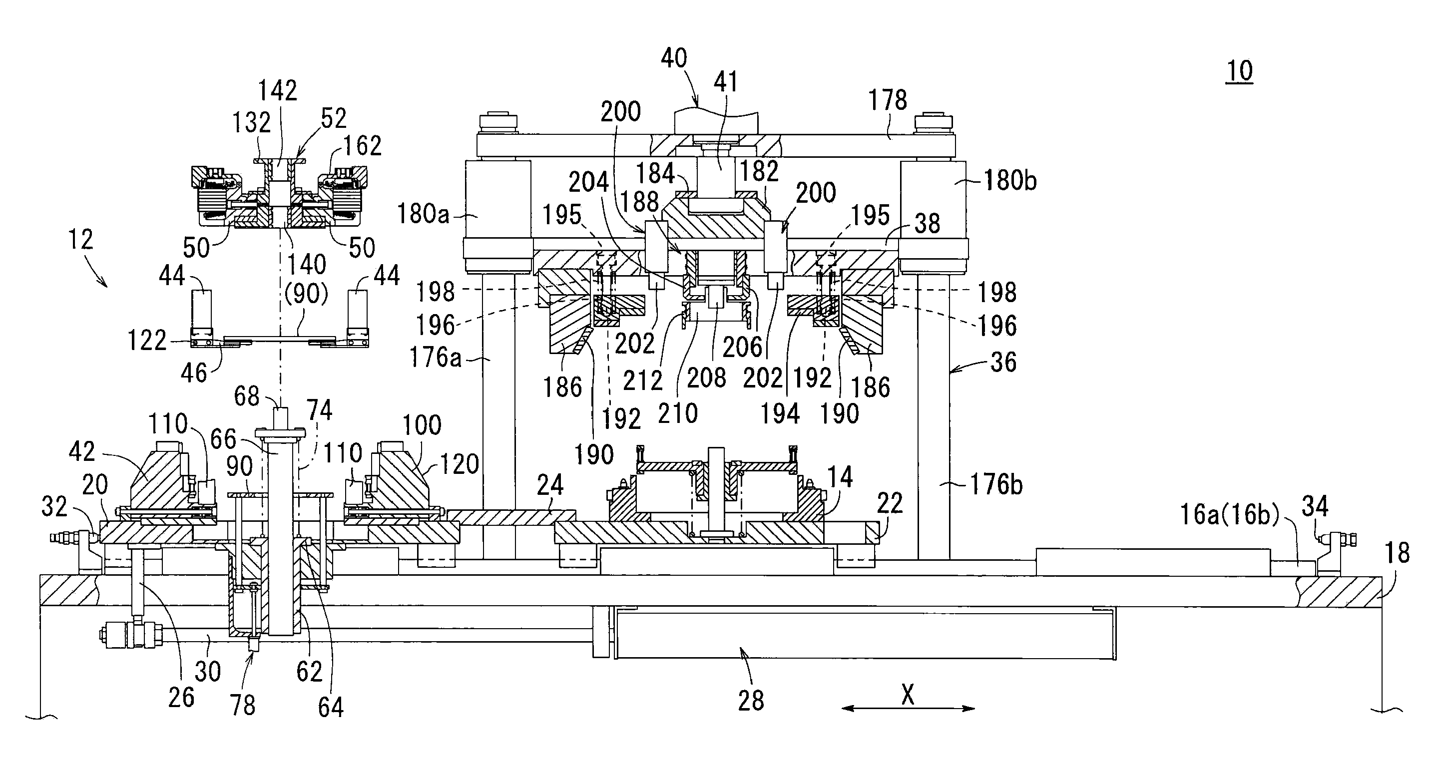
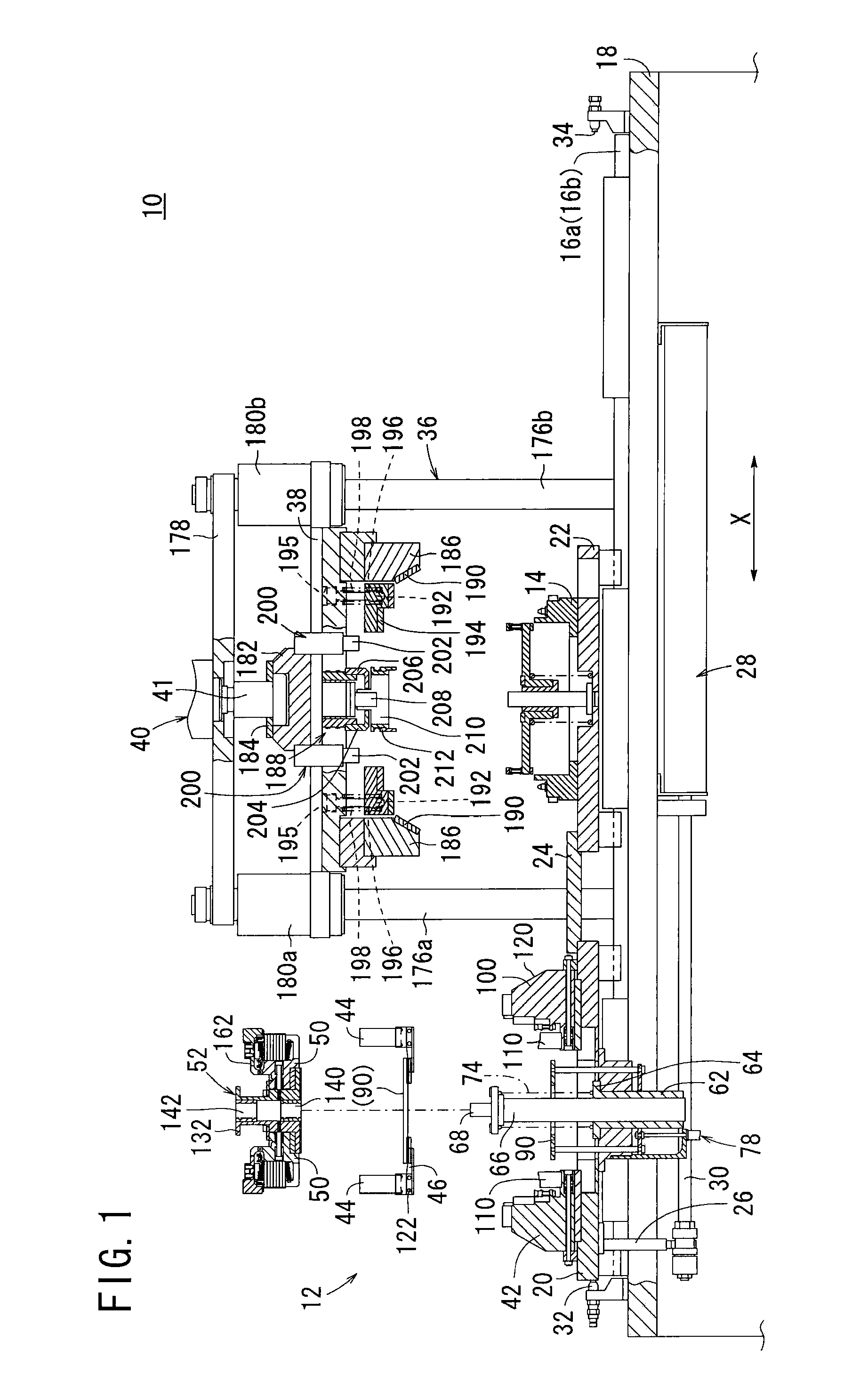
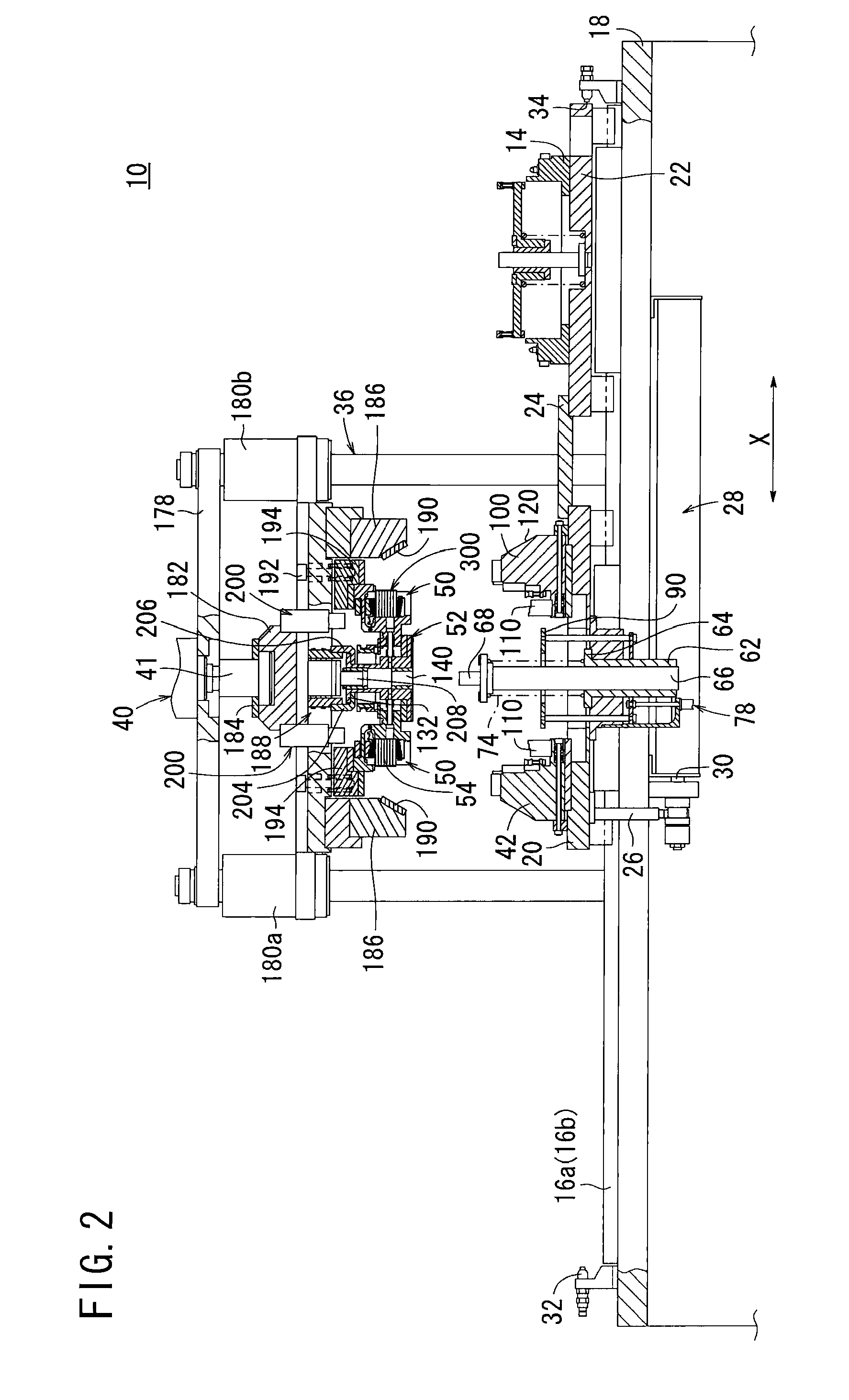
[0044]FIG. 1 is a front elevational view, partially in cross section, of a station 12 including a stator manufacturing apparatus 10 according to an embodiment of the present invention. The station 12 doubles as a manufacturing station for producing a stator, and an accommodating station for placing the produced stator inside a casing 14.

[0045]Specifically, the station 12 includes a base 18 with a pair of guide rails 16a, 16b mounted on an upper surface thereof. The stator manufacturing apparatus 10 includes a base plate 20 slidably mounted on the guide rails 16a, 16b. The casing 14 is positioned on and fixed to a table 22, which is slidably mounted on the guide rails 16a, 16b. The base plate 20 and the table 22 are connected to each other by a connector 24. The base plate 20 has a lower surface coupled by a ...


PUM

PropertyMeasurementUnit
sizeaaaaaaaaaa
diametersaaaaaaaaaa
timeaaaaaaaaaa

Abstract

A stator manufacturing apparatus for manufacturing a stator efficiently includes a base plate, a plurality of radially inward displacing jigs disposed radially in an annular pattern on the base plate and which are radially displaceable toward and away from each other, a plurality of core holding jigs disposed radially inward of the radially inward displacing jigs and which are radially displaceable toward and away from each other, a movable plate disposed vertically upward of the base plate and which is vertically movable toward and away from the base plate, a cam disposed on the movable plate for displacing the radially inward displacing jigs radially toward each other when the movable plate is lowered, and a spacer holding jig for holding spacers that are inserted between adjacent separate cores.

Description

BACKGROUND OF THE INVENTION[0001]1. Field of the Invention[0002]The present invention relates to a stator manufacturing apparatus for joining a plurality of separate cores, each carrying a coil wound thereon, into an annular stator.[0003]2. Description of the Related Art[0004]Heretofore, there has been known a stator for electric rotary machines, which comprises a plurality of interconnected separate cores. Each of the separate cores comprises an arcuate yoke, a pole extending radially inward from the yoke, and a coil wound around the pole.[0005]The yoke for each of the separate cores has a recess defined in a portion thereof, and a tooth provided on another portion thereof. The recess of the yoke of one of the separate cores receives therein the tooth of the yoke of an adjacent right-hand separate core, and also receives the tooth of the yoke of one of the separate cores that is fitted into the recess of the yoke of an adjacent left-hand separate core. The yokes are thus interconne...

Claims


Application Information

Patent Timeline
Patent Type & Authority Applications(United States)
IPC IPC(8): H02K15/02
CPCH02K15/022Y10T29/53143Y10T29/53978Y10T29/5317
Inventor SAKAKIABARA, HIROSHI
Owner HONDA MOTOR CO LTD
Learn More