Bushing for Nail Guns

a nail gun and nail gun technology, applied in the field of nail gun spouting, can solve the problems of unstable control of nail gun nailing motion, increased difficulty in spouting, so as to reduce the complexity of the air flow passage and improve the stability of controlling the nail gun spouting motion.

Inactive Publication Date: 2010-01-28
DE POAN PNEUMATIC
View PDF18 Cites 3 Cited by
  • Summary
  • Abstract
  • Description
  • Claims
  • Application Information

AI Technical Summary

Benefits of technology

[0004]To overcome aforementioned problem, an object of the present invention is to provide a bushing mounted in a nail gun. The air flow passage is integrally formed in the bushing so as to improve a stability of controlling of nail hitting motion and reduce a complexity of the air flow passage.

Problems solved by technology

The structure of the air flow passage is too complicated.
As a result, controlling of nail hitting of the nail gun is unstable.
This issue becomes significant especially after the nail gun has been used for a period due to abrasion between different parts.
In addition, a cost of manufacturing such an air flow passage is also very high.

Method used


Image

  • Bushing for Nail Guns
  • Bushing for Nail Guns
  • Bushing for Nail Guns

Examples


Embodiment Construction

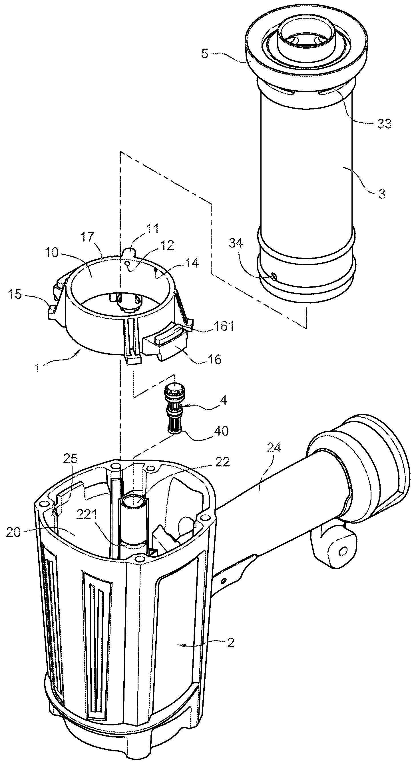
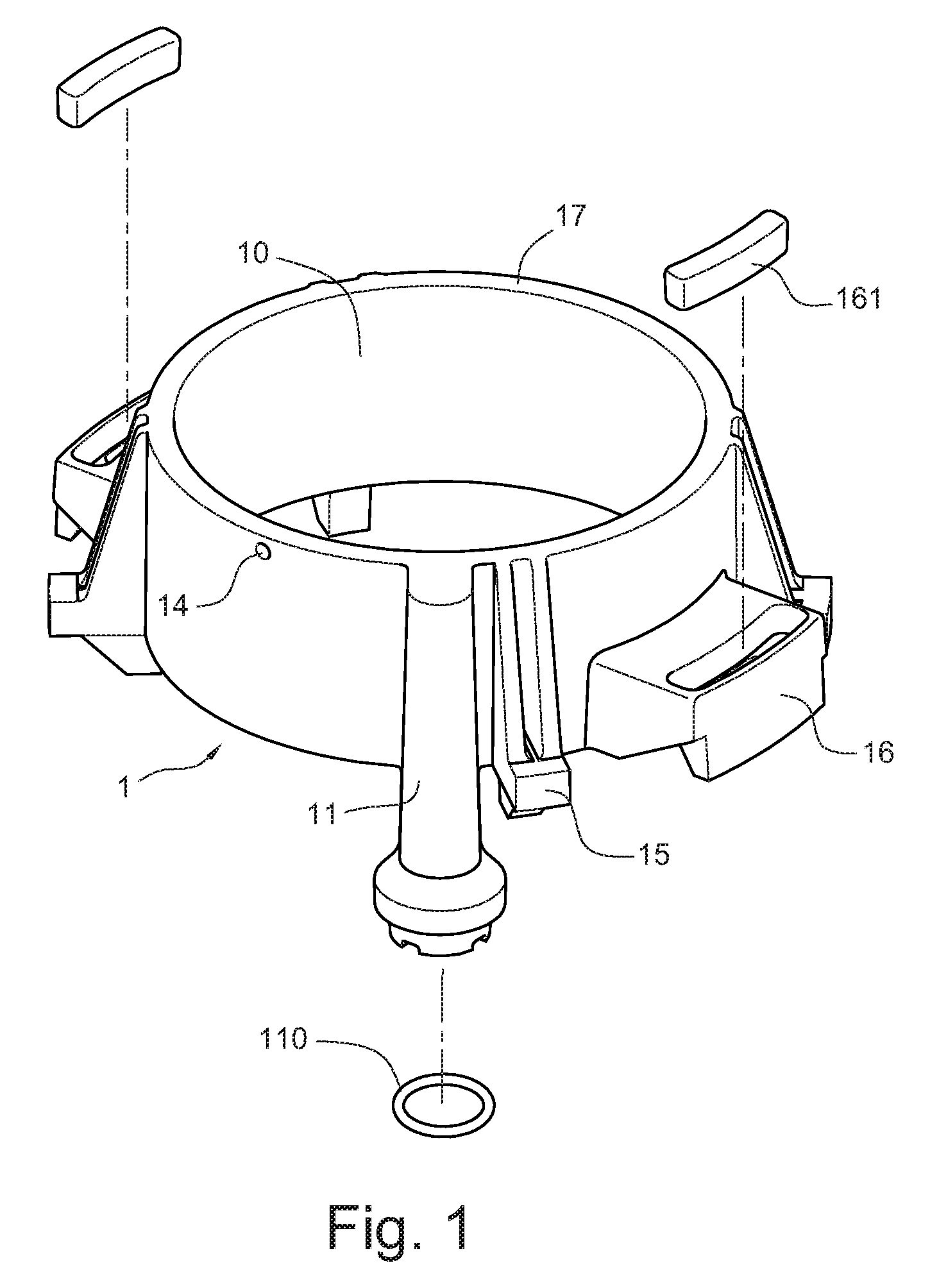
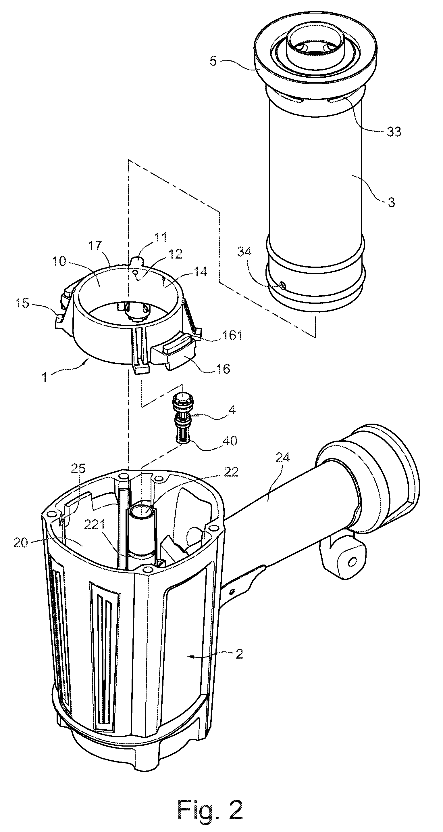
[0022]FIG. 1 illustrates an exploded view of a bushing 1 for a nail gun in accordance with a first embodiment. Referring to FIG. 2 together, the bushing 1 is between an air chamber 20 in a housing 2 of the nail gun and a movable cylinder 3 (referring together with FIG. 4). The bushing 1 is also adjacent to a bottom of a main valve 5 which is configured for driving hitting motion of the nail gun. A top of a sidewall of the cylinder 3 includes a number of main valve holes 33 formed therein. The main valve holes 33 are adjacent to the main valve 5. A bottom of the sidewall of the cylinder 3 includes at least one air inlet 34 formed therein. The air inlet is communication with an inner chamber of the cylinder. An air flow passage 21 (as shown in FIG. 5) is formed in the housing 2. The air flow passage 21 is between and in communication with the main valve holes 33 and the air inlet 34. The air flow passage 21 receives a valve plug 4 that is capable of opening or blocking the air flow pa...


PUM


Abstract

A bushing for conducting air in a nail gun is arranged between an air chamber and a cylinder received in a housing of the nail gun. The bushing is adjacent to a bottom of a main valve for driving hitting motion of the nail gun. A number of main valve holes that are adjacent to the main valve are formed in a sidewall of the cylinder. At least one air inlet is formed in a bottom of a sidewall of the cylinder. An air flow passage is defined in the housing and is in communication with the main valve and the air hole. A valve plug which is configured for opening or closing the air flow passage is received in the air flow passage. The valve plug divides the air flow passage into an upper portion and a lower portion. The lower portion is formed in the housing. An annular end surface is formed on a top of the bushing. The annular end surface defines a main air inlet for the main valve. An end portion extends from the bushing and having the upper portion of the air flow passage formed therein. The bushing further includes at least one upper air hole in communication with the air chamber, the main inlet and the upper portion of the air flow passage.

Description

BACKGROUND[0001]Generally, nail guns have an air chamber for collecting pressurized air from an air source as a power source for nail guns and a cylinder mounted in a housing. The cylinder may be movably relative to the housing or be fixed on the housing. The cylinder includes a piston slidably disposed therein. The piston divides an inner chamber of the cylinder into a top cylinder chamber and a lower cylinder chamber. The nail gun also includes a trigger valve that is capable of being triggered by pressing so as to drive nail hitting action of the nail gun. The pressurized air in the air chamber enters into the top cylinder chamber to press the piston move downwardly when a trigger of the trigger valve is pressed. The pressurized air in the top cylinder chamber vents from the top cylinder chamber and enters into the lower cylinder chamber to drive the piston move upwardly to its original position.[0002]Nail guns employing movable cylinders have been developed, for example, U.S. Pa...

Claims


Application Information

Patent Timeline
Patent Type & Authority Applications(United States)
IPC IPC(8): B25C1/04F15B15/20
CPCB25C1/045
Inventor LIANG, CHIA-SHENGKUO, LUN-HUNG
Owner DE POAN PNEUMATIC
Why Eureka
Try Eureka