
Set battery control method and set battery control circuit as well as charging circuit and battery pack having the set battery control circuit

Inactive Publication Date: 2010-01-28
PANASONIC CORP
View PDF5 Cites 23 Cited by
  • Summary
  • Abstract
  • Description
  • Claims
  • Application Information

AI Technical Summary

Benefits of technology

[0017]An object of the invention is to provide a set battery control method and a set battery control circuit capable of lessening a difference among the terminal voltages across the respective secondary batteries while reducing the possibility that the most deteriorated secondary battery is deteriorated further as well as a charging circuit and a battery pack having the set battery control circuit.
[0018]A set battery control circuit according to one aspect of the invention includes: a voltage detection portion that detects a terminal voltage across each secondary battery in a set battery formed by connecting a plurality of secondary batteries in series; a discharge portion that discharges the plurality of secondary batteries; and an imbalance reduction processing portion that performs imbalance reduction processing at set timing preset as timing at which terminal voltages across the plurality of secondary batteries become voltages at or below a cut-off voltage of discharge preset as a voltage at which discharge is to end in such a manner that a secondary battery having a terminal voltage higher than a lowest voltage, which is a lowest terminal voltage among the terminal voltages across the plurality of secondary batteries detected by the voltage detection portion, is discharged by means of the discharge portion so that a difference among the terminal voltages across the respective secondary batteries is lessened.
[0021]Hence, by discharging a secondary battery having the terminal voltage higher than the lowest voltage, that is, a secondary battery thought to be less deteriorated than the secondary battery having the lowest terminal voltage, so as to lessen a difference among the terminal voltages across the respective secondary batteries, it becomes possible to lessen a difference among the terminal voltages across the respective secondary batteries while reducing the possibility that the most deteriorated secondary battery is discharged more and deteriorated further.
[0023]According to the charging circuit configured as above, when the user makes an operation to charge the set battery using the charge portion, that is, when it is highly likely that at least one of the terminal voltages across the plurality of secondary batteries has dropped to or below the cut-off voltage of discharge, the set battery is charged after the imbalance reduction processing is performed. It thus becomes possible to lessen a difference among the terminal voltages across the respective secondary batteries while reducing the possibility that the most deteriorated secondary battery is discharged more and deteriorated further. In addition, by charging the set battery in a state where a difference among the terminal voltages across the respective secondary batteries is lessened, it becomes possible to reduce a cumulative increase of an imbalance among the secondary batteries.
[0025]According to the battery pack configured as above, because the imbalance reduction processing can be performed in the battery pack, it becomes possible to lessen a difference among the terminal voltages across the respective secondary batteries while reducing the possibility that the most deteriorated secondary battery is discharged more and deteriorated further in the battery pack.
[0027]According to the battery pack configured as above, when the user makes an operation to charge the set battery using the charge portion, that is, when the terminal voltage across the most deteriorated secondary battery is thought to be the lowest voltage, the set battery can be charged by the charge device after a difference among the terminal voltages across the respective batteries is lessened by performing the imbalance reduction processing. It thus becomes possible to reduce a cumulative increase of an imbalance among the secondary batteries by charging the set battery using the charge device in a state where a difference among the terminal voltages across the respective secondary batteries is lessened while reducing the possibility that the most deteriorated secondary battery is discharged more and deteriorated further.

Problems solved by technology

Incidentally, the internal resistance of a secondary battery increases when it deteriorates.
In a case where a secondary battery is discharged, the secondary battery deteriorates when it is overdischarged.
This causes an inconvenience that the capacities of the less deteriorated secondary batteries 112 and 113 are not utilized effectively and the capacity of the overall set battery is reduced.
This causes an inconvenience that a difference among the terminal voltages α11, α12, and α13 becomes larger.
This causes an inconvenience that deterioration varies considerably among the secondary batteries 111, 112, and 113 and an imbalance is increased.
In addition, as a secondary battery deteriorates further, the capacity decreases and the terminal voltage drops faster at the time of discharge.
This causes an inconvenience that there is a possibility that a difference among the terminal voltages α11, α12, and α13 across the secondary batteries 111, 112, and 113, respectively, is increased and so is an imbalance.

Method used


Image

  • Set battery control method and set battery control circuit as well as charging circuit and battery pack having the set battery control circuit
  • Set battery control method and set battery control circuit as well as charging circuit and battery pack having the set battery control circuit
  • Set battery control method and set battery control circuit as well as charging circuit and battery pack having the set battery control circuit

Examples


first embodiment

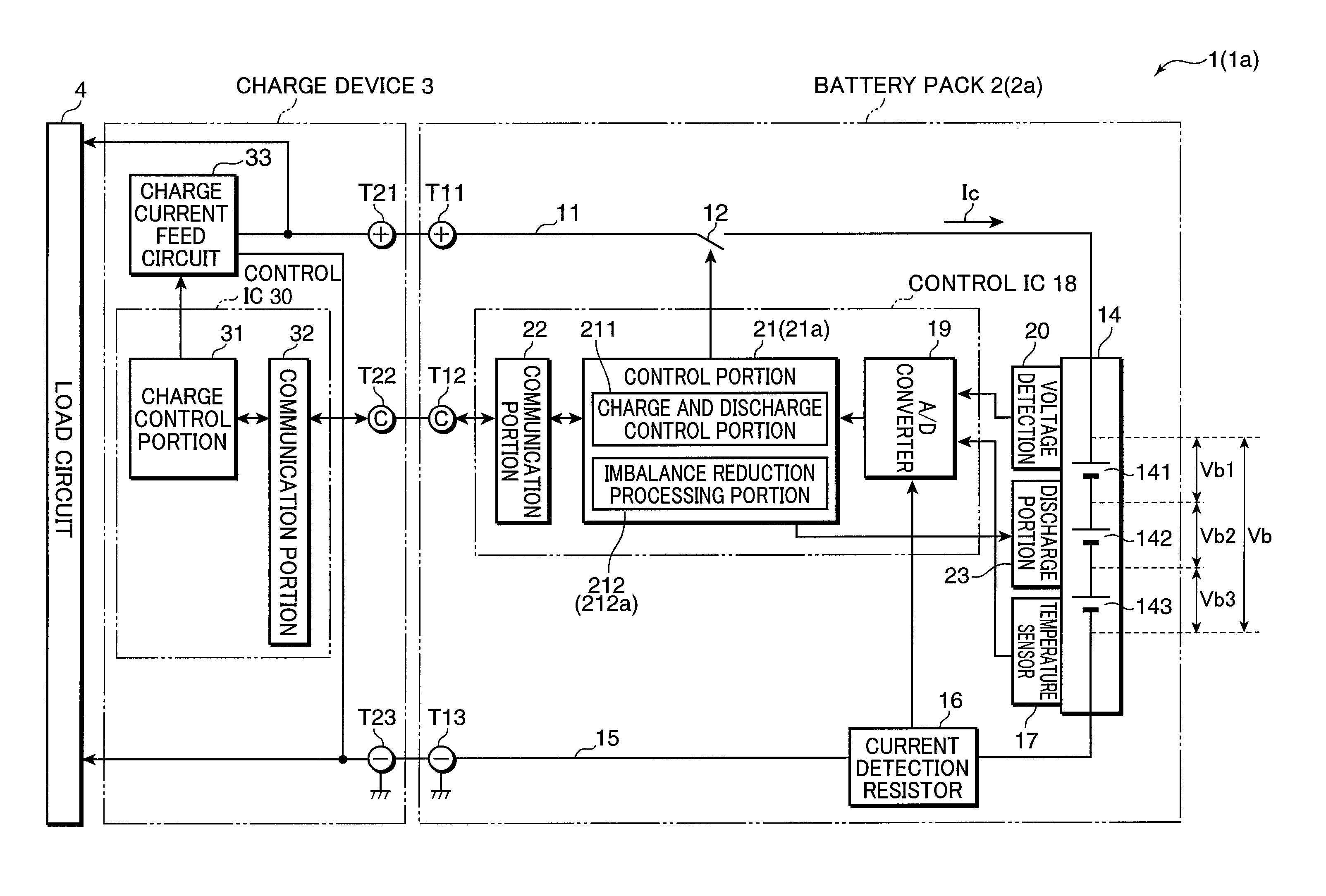
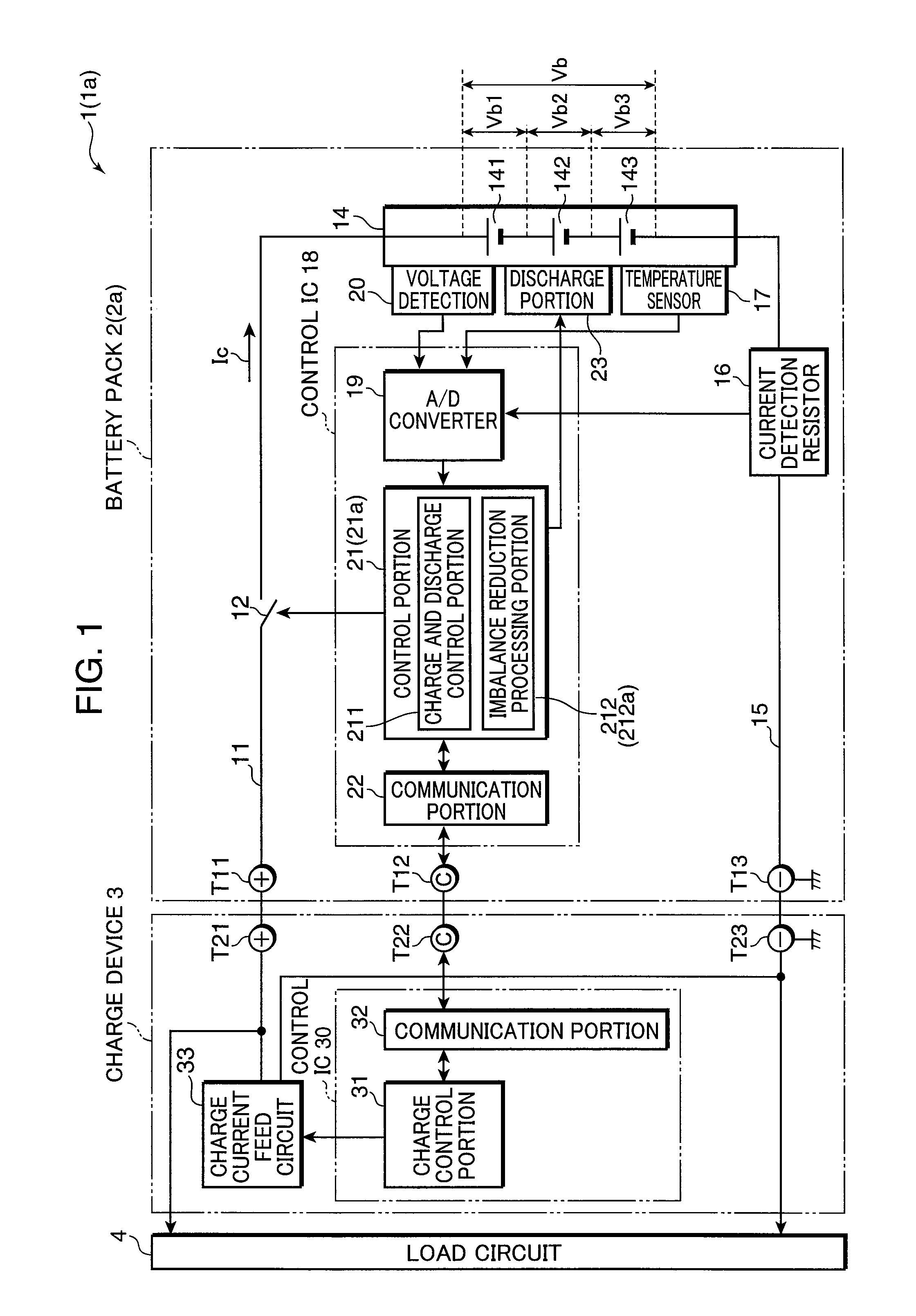
[0036]FIG. 1 is a block diagram showing an example of the configuration of a charge system 1 using a battery pack 2 having a set battery control circuit according to one embodiment of the invention. The charge system 1 includes the battery pack 2 and a charge device 3 that charges the battery pack 2. However, the battery pack 2 and the charge device 3 are not necessarily separated from each other and it may be configured in such a manner that, as is shown in FIG. 1, the battery pack 2 and the charge device 3 are formed integrally into one circuit. Alternatively, it may be formed as an electric equipment system by further including a load circuit 4 to which power is fed from the battery pack 2. The battery pack 2 is charged by the charge device 3 in FIG. 1. However, the battery pack 2 may be attached to the load circuit 4, so that it is charged via the load circuit 4. The battery pack 2 and the charge device 3 are connected to each other by terminals T11 and T21 on the DC (Direct Cur...

second embodiment

[0072]A charge system 1 a using a charging circuit according to a second embodiment of the invention will now be described. As with the charge system 1, the charge system 1a is shown in FIG. 1. The charge system la is different from the charge system 1 in the timing at which the imbalance reduction processing is performed by an imbalance reduction processing portion 212a in a battery pack 2a. The charge device 3 corresponds to an example of the charge portion. The voltage detection circuit 20, the discharge portion 23, and the imbalance reduction processing portion 212a correspond to an example of the set battery control circuit. The charge and discharge control portion 211, the voltage detection circuit 20, the discharge portion 23, and the imbalance reduction processing portion 212a correspond to an example of the charging circuit.

[0073]As with the charge system 1, the charge system 1a may be formed of the battery pack 2a and the charge device 3 that are formed integrally into one...


PUM


Abstract

A set battery control circuit includes: a voltage detection portion that detects a terminal voltage across each secondary battery in a set battery formed by connecting a plurality of secondary batteries in series; a discharge portion that discharges the plurality of secondary batteries; and an imbalance reduction processing portion that performs imbalance reduction processing at set timing preset as timing at which terminal voltages across the plurality of secondary batteries become voltages at or below a cut-off voltage of discharge preset as a voltage at which discharge is to end in such a manner that a secondary battery having a terminal voltage higher than a lowest voltage, which is a lowest terminal voltage among the terminal voltages across the plurality of secondary batteries detected by the voltage detection portion, is discharged by means of the discharge portion so that a difference among the terminal voltages across the respective secondary batteries is lessened.

Description

TECHNICAL FIELD [0001]The present invention relates to a set battery control method and a set battery control circuit configured to reduce an imbalance in a set battery formed by connecting a plurality of secondary batteries in series as well as a charging circuit and a battery pack having the set battery control circuit.BACKGROUND ART [0002]FIG. 6 shows a case where a set battery formed by connecting a plurality of secondary batteries in series is charged and discharged by a charge and discharge method for a secondary battery in the background art, and it is a graph showing, for example, changes of terminal voltages α11, α12, and α13 across three secondary batteries 111, 112, and 113, respectively.[0003]Initially, at timing T101, the terminal voltages α11, α12, and α13 across the secondary batteries 111, 112, and 113, respectively, are all equal at a cut-off voltage of discharge, Vt (for example, 3.0 V) and the secondary batteries 111, 112, and 113 are in a balanced state. When a c...

Claims


Application Information

Patent Timeline
IPC IPC(8): H02J7/00H02J7/02H02J7/34
CPCH02J7/0016
Inventor NAKATSUJI, TOSHIYUKI
Owner PANASONIC CORP
Features
  • Generate Ideas
  • Intellectual Property
  • Life Sciences
  • Materials
  • Tech Scout
  • Unparalleled Data Quality
  • Higher Quality Content
  • 60% Fewer Hallucinations
Learn More