Fluorescence endoscope

a fluorescence endoscope and endoscope technology, which is applied in the field of fluorescence endoscopes, can solve the problems of difficult to maintain a constant distance between the surface of the lumen and the detection unit of the endoscope, and difficult to make a diagnosis of a lesion using fluorescence intensity

Inactive Publication Date: 2010-01-28
OLYMPUS CORP
View PDF9 Cites 14 Cited by
  • Summary
  • Abstract
  • Description
  • Claims
  • Application Information

AI Technical Summary

Benefits of technology

The fluorescence endoscope described in this patent can create the same image signal even if the distance between the endoscope and the inner wall of the body cavity changes. This makes it easier to determine if the tissue in the body cavity is cancerous or not.

Problems solved by technology

The patent text discusses the use of medicinal agents that generate fluorescence to diagnose diseased areas in body tissue, such as cancer. However, it can be difficult to accurately diagnose the area due to the inverse relationship between fluorescence intensity and distance between the detecting unit and the affected area. Various methods have been proposed to maintain a constant distance between the detecting unit and the diseased area for accurate diagnosis. The patent text also mentions a technology for examining vascular tissue by using a probe with a balloon to maintain contact with the vessel wall. Additionally, a technology is described that uses distance measurement and characteristic-value calculation to diagnose lesions without being affected by the distance between the irradiating unit and the subject.

Method used


Image

  • Fluorescence endoscope
  • Fluorescence endoscope
  • Fluorescence endoscope

Examples


first embodiment

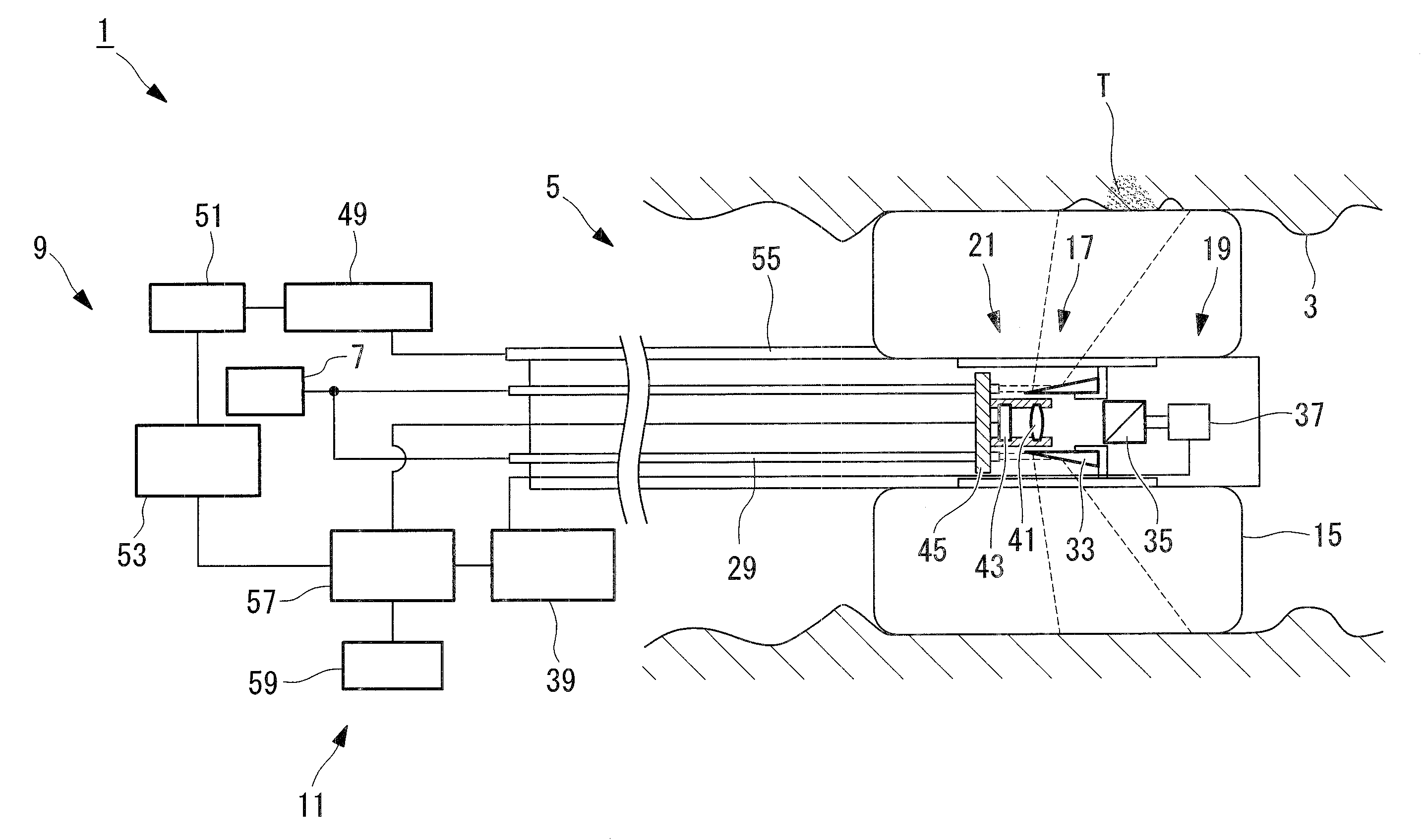
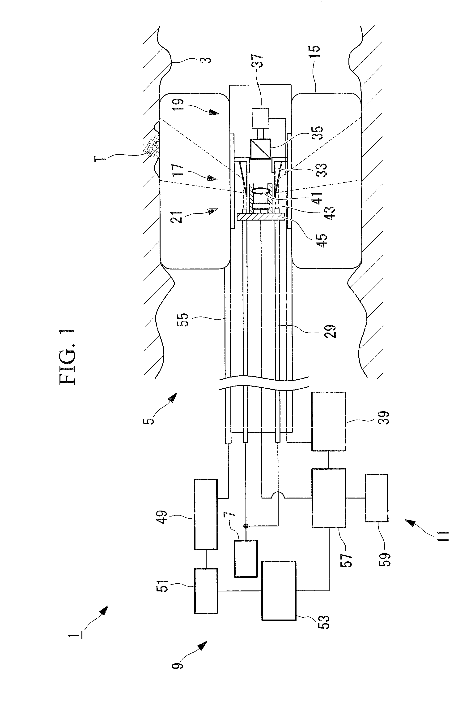
[0108]A fluorescence endoscope according to a first embodiment of the present invention will be described below with reference to FIGS. 1 to 7.

[0109]FIG. 1 is a view for explaining the structure of the fluorescence endoscope of this embodiment.

[0110]As shown in FIG. 1, a fluorescence endoscope 1 includes an insertion portion 5 that is to be inserted into a body cavity 3 of a subject, a light source 7 that emits excitation light, a measurement control unit 9 that measures the distance between the insertion portion 5 and an inner wall of the body cavity 3, and a display unit 11 that displays an acquired fluorescence image.

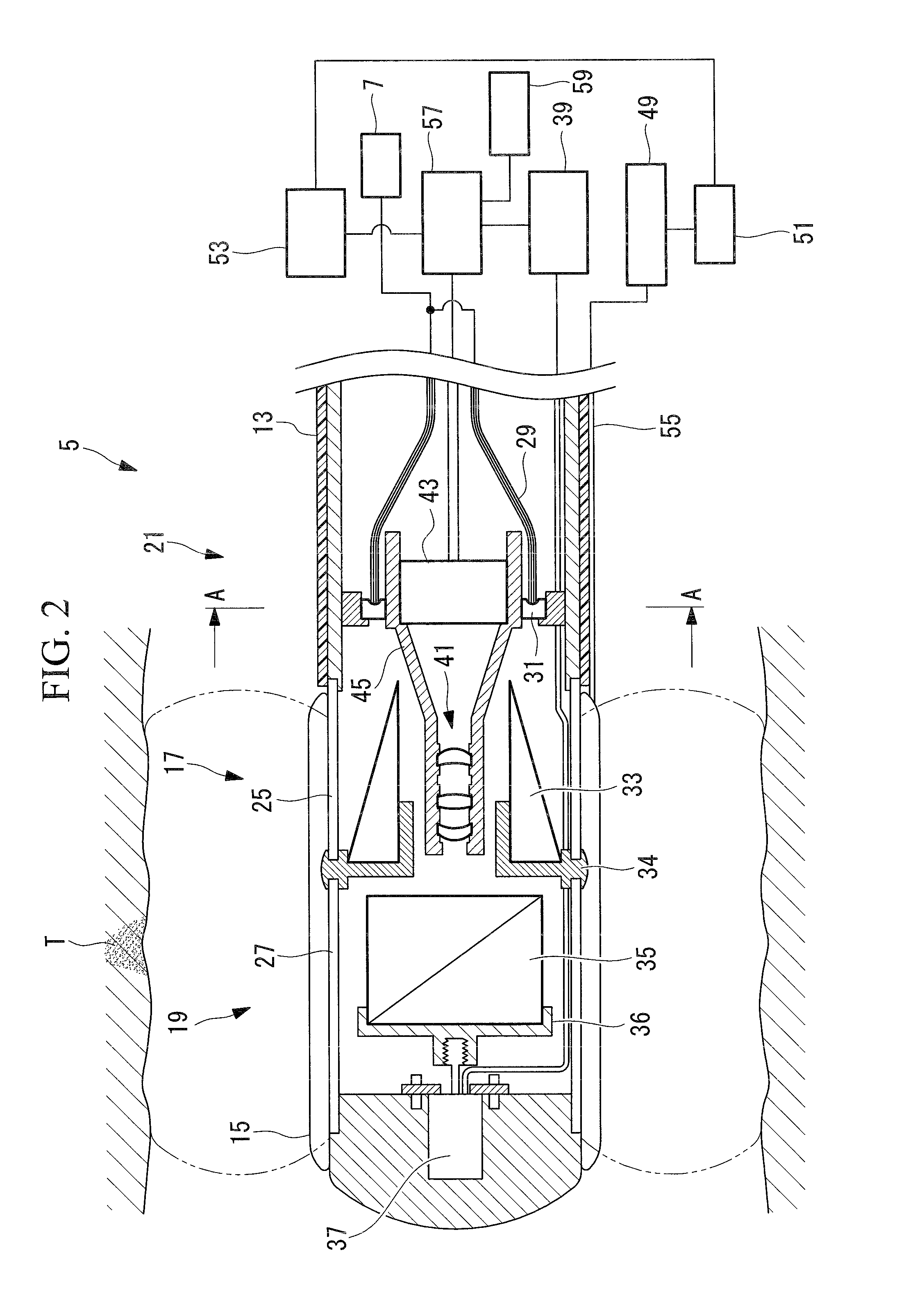
[0111]FIG. 2 is a view for explaining the structure of the insertion portion shown in FIG. 1.

[0112]The insertion portion 5 is inserted into the body cavity 3 of the subject and observes fluorescence generated at the inner wall of the body cavity 3. As shown in FIG. 2, the insertion portion 5 is provided with a casing tube 13, a balloon 15, a light emitting part (ligh...

third modification

of First Embodiment

[0211]Next, a third modification of the first embodiment of the present invention will be described with reference to FIGS. 14 and 15.

[0212]Although the basic structure of a fluorescence endoscope of this modification is the same as that of the second modification of the first embodiment, the structure of a rotary insertion portion of this modification is different from that of the first embodiment. Therefore, in this modification, only the rotary insertion portion and the components surrounding it will be described with reference to FIGS. 14 and 15, and a description of the other components will be omitted.

[0213]FIG. 14 is a view for explaining the structure of the fluorescence endoscope according to this modification.

[0214]Note that the same reference symbols are given to the same components as those of the second modification of the first embodiment, and a description thereof will be omitted.

[0215]As shown in FIG. 14, a fluorescence endoscope 901 includes an in...

fourth modification

of First Embodiment

[0238]Next, a fourth modification of the first embodiment of the present invention will be described with reference to FIGS. 16 to 18.

[0239]Although the basic structure of a fluorescence endoscope of this modification is the same as that of the second modification of the first embodiment, the structure of an inner insertion portion of this modification is different from that of the first embodiment. Therefore, in this modification, only the inner insertion portion and the components surrounding it will be described with reference to FIGS. 16 to 18, and a description of the other components will be omitted.

[0240]FIG. 16 is a view for explaining the structure of the fluorescence endoscope according to this modification.

[0241]Note that the same reference symbols are given to the same components as those of the second modification of the first embodiment, and a description thereof will be omitted.

[0242]As shown in FIG. 16, a fluorescence endoscope 301 includes an inse...


PUM


Abstract

A fluorescence endoscope is provided that can easily judge whether body-cavity tissue is benign or malignant when fluorescence generated at the entire inner circumferential face of the body cavity serving as a subject is observed. The fluorescence endoscope includes: an insertion portion (5) be inserted into a body cavity (3); a balloon (15) brought into contact with an inner wall of the body cavity (3) located in radial directions of the insertion portion (5), thereby positioning the insertion portion (5) with respect to the body cavity (3) in the radial directions of the insertion portion (5); a light emitting and introducing unit (17, 19) emits excitation light for irradiating the inner wall, outward in the radial directions of the insertion portion (5), and introduces fluorescence generated at the inner wall to the inside of the insertion portion (5) from a plurality of different radial directions of the insertion portion (5); an image-acquisition unit (21) acquires an image with the fluorescence introduced by the light emitting and introducing unit (17, 19); a correction-signal calculating unit (57) calculates a correction signal for correcting an image-acquisition signal output from the image-acquisition unit (21), based on a distance between the insertion portion (5) and a contact surface of the balloon (15) that is brought into contact with the inner wall; and a signal processing unit (57) corrects the intensity of the image-acquisition signal based on the correction signal and generates an image signal from the corrected image-acquisition signal.

Description


Claims


Application Information

Patent Timeline
Owner OLYMPUS CORP
Why Eureka
Try Eureka