Imaging apparatus and method

Active Publication Date: 2010-01-28
FUJIFILM CORP
View PDF8 Cites 21 Cited by
  • Summary
  • Abstract
  • Description
  • Claims
  • Application Information

AI Technical Summary

Benefits of technology

[0028]According to the present invention, processing for determining what kind of scene a particular scene is, and processing for monitoring whether a scene change has occurred compared to a scene when the recognition has bee

Problems solved by technology

Therefore, the processing becomes less efficient compared to the case where the processing is performed when necessary.
Therefore, an

Method used


Image

  • Imaging apparatus and method
  • Imaging apparatus and method
  • Imaging apparatus and method

Examples


first embodiment

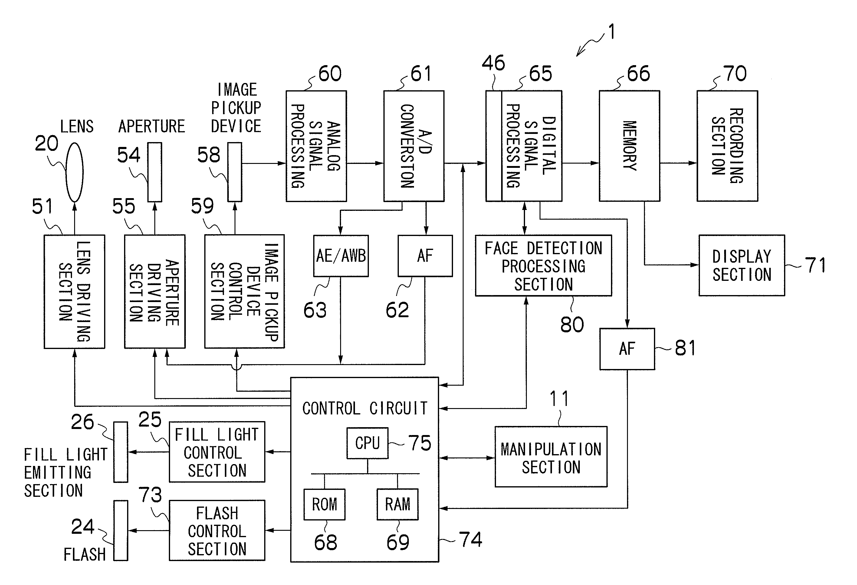
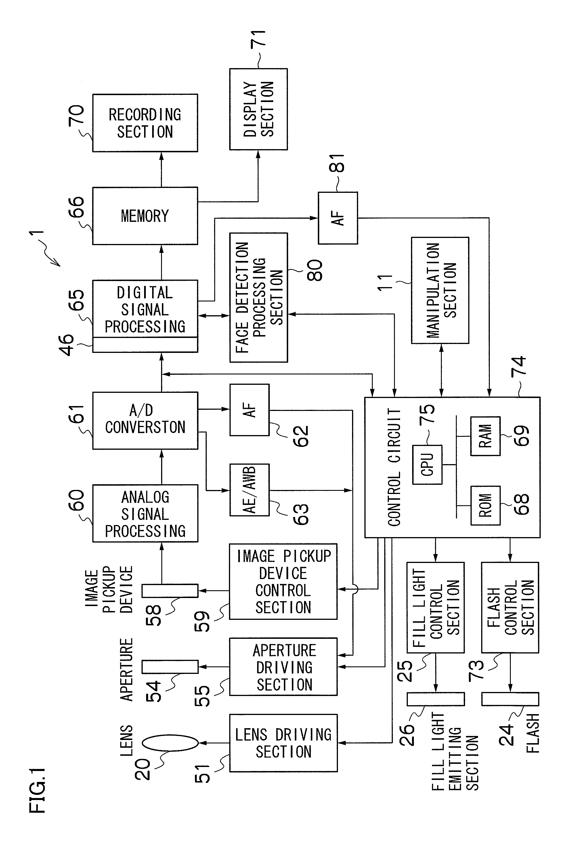
[0066]FIG. 1 is a schematic block diagram showing a configuration of a digital camera 1 according to the present invention. A digital camera 1 converts image data acquired through photography into an Exif-format image file and records the Exif-format image file into a recording section 70 such as an external recording medium that is attachable / detachable to a main body.

[0067]A manipulation system of the digital camera includes: a manipulation section 11 having an operating mode switch, a menu / OK button, a zoom / upward / downward arrow lever, a leftward / rightward arrow button, a Back (return) button, a display switching button, a shutter button, a power switch, and the like; and a control circuit 74 that interprets contents of manipulations performed on the manipulation section 11 and controls the respective sections. The control circuit 74 includes: a CPU 75 which performs information processing; a ROM 68 on which are recorded programs defining information processing, firmware, constan...

second embodiment

[0275]FIG. 17 is a flowchart of a frame change check subroutine according to a second embodiment. This processing can be executed in place of the processing shown in FIG. 3. Execution of the processing is controlled by the CPU 75 of the digital camera 1. A program defining the processing is stored in the ROM 68.

[0276]S201 to S203 are the same as S21 to S23.

[0277]In S204, a value obtained by adding a weight E_AUTOSP_FRAME_CHECK1 corresponding to the first frame change check to the parameter “change_measure” in the RAM 69 is set as the new “change measure”. E_AUTOSP_FRAME_CHECK1 is stored in advance in the ROM 68.

[0278]S205 to S207 are the same as S25 to S27.

[0279]In S208, a value obtained by adding a weight E_AUTOSP_FRAME_CHECK2 corresponding to the second frame change check to the parameter “change measure” in the RAM 69 is set as the new “change measure”. E_AUTOSP_FRAME_CHECK2 is stored in advance in the ROM 68.

[0280]S209 to S211 are the same as S29 to S31.

[0281]In S212, a value ob...

third embodiment

[0289]FIG. 19 is a flowchart of main processing according to a third embodiment. This processing can be executed in place of the processing shown in FIG. 2. Execution of the processing is controlled by the CPU 75 of the digital camera 1. A program defining the processing is stored in the ROM 68. In this embodiment, frame change check (single frame change check) are performed based on frame change reference information and photographic information a plurality of times, and further, the frame change check results are accumulated as frame change history record, and frame change check (total frame change check) is performed based on the frame change history record.

[0290]S301 to S303 are the same as Si to S3. However, in S302, frame change history record is also initialized.

[0291]In S304, frame change history record stored in RAM 69 is advanced to older side by one generation. In other words, frame change check results in frame change history record are shifted. In STATE A in FIG. 20, as...


PUM


Abstract

To output stable results as necessary when recognizing scenes with a camera. Unless the result of scene recognition can be stabilized, an output result will confuse the user. In consideration thereof, by combiningly performing processing for determining what type of scene a particular scene is and processing for monitoring whether or not a change has occurred from a recognized scene, it is now possible to perform scene recognition in an accurate and stable manner.

Description

BACKGROUND OF THE INVENTION[0001]1. Field of the Invention[0002]The present invention relates to an imaging apparatus including a photographic scene recognition function.[0003]2. Description of the Related Art[0004]In Japanese Patent Application Laid-Open No. 2003-244530, whether or not an actual photographic scene is appropriate with respect to a set photographic mode is judged based on a digital image signal loaded via a CCD or on an EV value. When the photographic mode is appropriate, a digital camera performs photographic processing in the photographic mode and records information on the photographic mode on a header portion of image data. When the photographic mode is inappropriate, the digital camera confirms with an operator as to whether or not photography is to be carried out in the set photographic mode and transitions to photographic processing, and either confirms with an operator as to whether or not the photographic mode information is to be recorded on the header port...

Claims


Application Information

Patent Timeline
IPC IPC(8): H04N5/228H04N5/14
CPCH04N5/14H04N5/147H04N5/23293H04N5/23219H04N5/23222H04N5/232H04N23/673H04N23/61H04N23/64H04N23/611H04N23/633
Inventor SUGIMOTO, MASAHIKO
Owner FUJIFILM CORP
Why Eureka
Try Eureka