Temperature measuring method in molten metal bath

a technology of molten metal bath and temperature measurement, which is applied in the direction of heat measurement, optical radiation measurement, instruments, etc., to achieve the effect of strong and more effective chang

Active Publication Date: 2010-01-28
HERAEUS ELECTRO NITE INT NV
View PDF11 Cites 12 Cited by
  • Summary
  • Abstract
  • Description
  • Claims
  • Application Information

AI Technical Summary

Benefits of technology

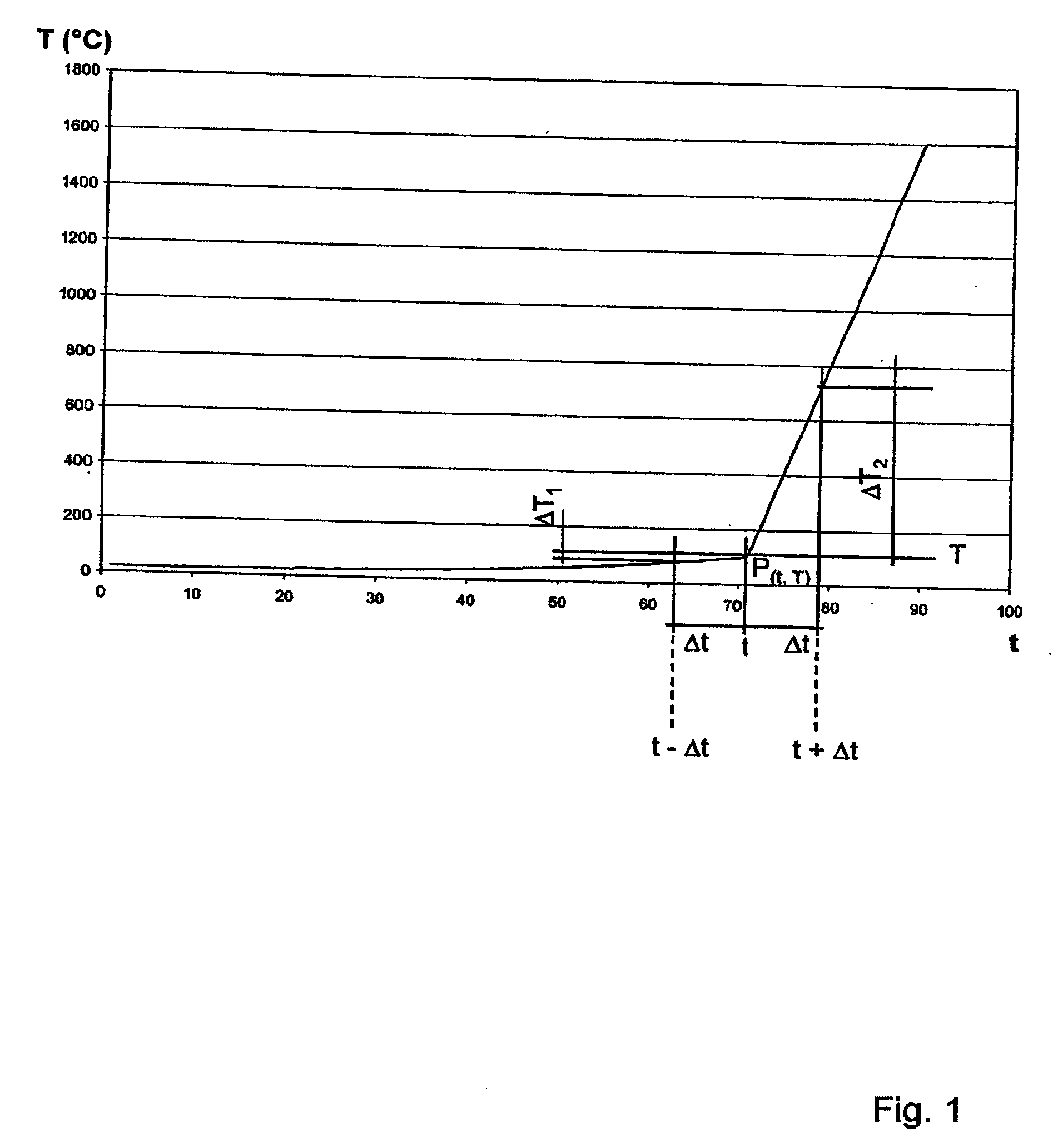
[0007]A temperature course of this kind means that from a particular point in time onwards the heating curve in principle has a bend (quasi discontinuity), at which the heating speed considerably increases compared with the previous course. It has been proved that a mechanical movement of the optical fiber or its immediate environment takes place, the magnitude of which depends on the size of the change in the heating speed and the shortness of the corresponding time interval. The greater the change in the heating speed and the smaller the time interval Δt is, the greater is the mechanical movement of the fiber or its immediate environment at the time of this quasi erratic change in the heating curve. This movement assists the immersion of the optical fiber in the molten bath and the replacing of the tip of the optical fiber, which is practically pushed off by the suddenly arising movement (vibration), so a new end of the glass fiber, not yet damaged by high temperatures, can be tracked.
[0009]It is appropriate that the temperature T0 of the optical fiber allocated to the point in time t0 between the two time intervals is a maximum of 600° C., preferably a maximum of 200° C., more preferably a maximum of 100° C. The temperature of the actual optical fiber in the narrower sense, in other words the temperature of the quartz glass should be considered in this. The lower this temperature T0, on which the change in the heating speed is based, the stronger and more effective this change can be.
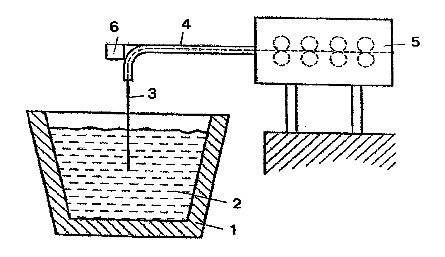
[0010]The speed at which the optical fiber is immersed in the molten metal bath or fed thereto corresponds to the speed at which the vitreous structure of its tip is destroyed, so new glass fiber material is constantly fed which is suitable for receiving and passing on radiation, without radiation losses arising owing to a destroyed fiber structure.
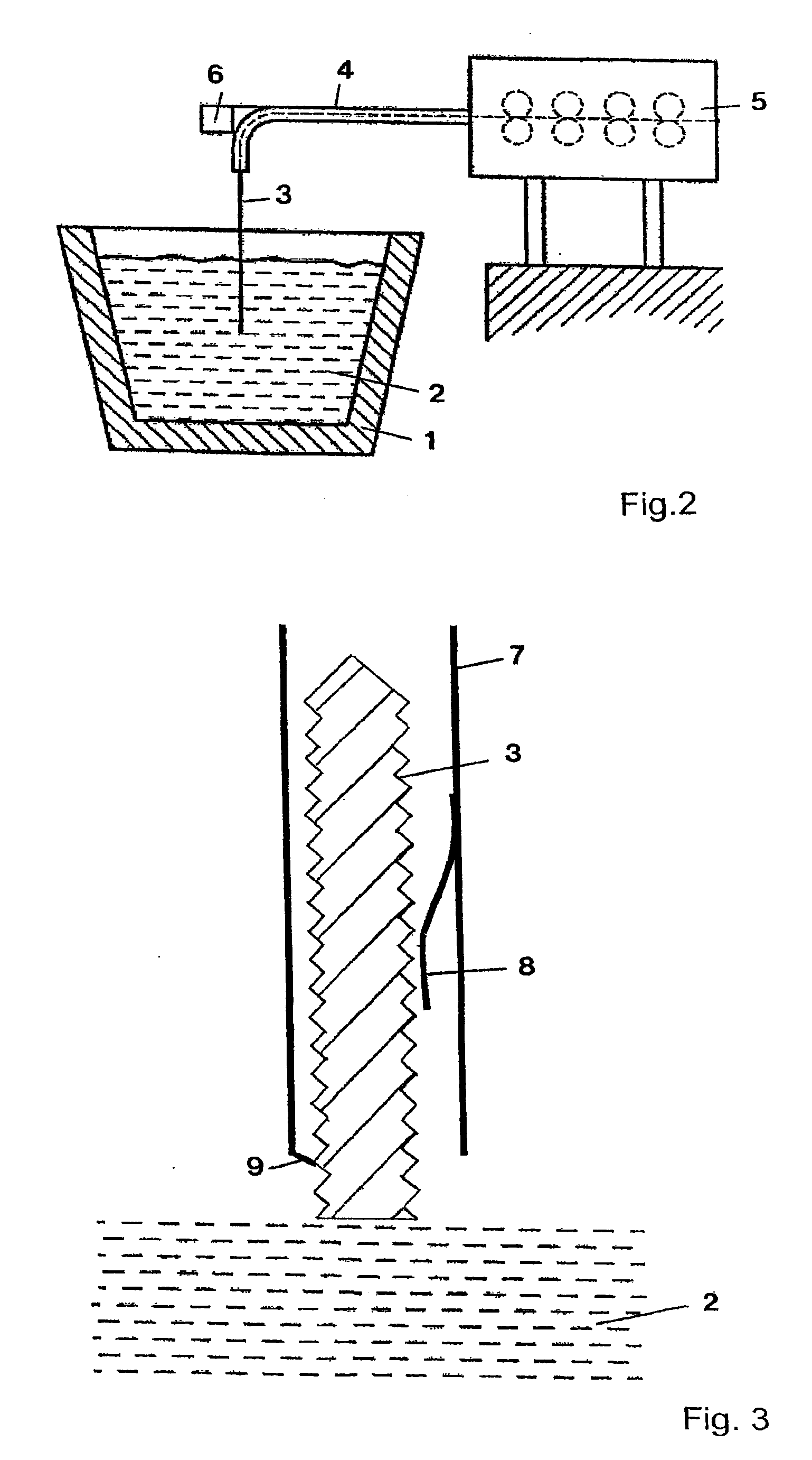
[0012]An intermediate layer of this kind is heated during the immersion of the optical fiber in the molten metal bath or a layer of slag above it. It has surprisingly been proved that the combination of a metal tube and an intermediate layer arranged beneath it, made of a powder or a fibrous or granular material, results in this material of the intermediate layer suddenly expanding greatly during heating, from a particular point onwards, in a heating curve with the presence of gases, namely if the metal tube is heated so much that it can no longer withstand the pressure which arises inside the metal tube, because of the expansion of the gases of the intermediate layer conditional on heat. In this case, fast rising stresses form inside the metal tube, until it suddenly cracks or is destroyed in some other way, so that the cover of the optical fiber moves away from the fiber practically explosively. In general, the device according to the invention is characterised in that during or after the destruction of the metal tube, the intermediate layer very quickly disintegrates as a layer, its parts moving away from the fiber. In this way, on the one hand the optical fiber is very quickly and suddenly exposed to the molten metal bath at its immersed end and on the other hand the advance of the tip of the optical fiber into the molten metal bath is made considerably easier.
[0014]The cover preferably has a vibrator or a vibrator is arranged on or next to the cover, to improve the release of the material of the cover from the optical fiber or the removal (breaking off) of the destroyed tip of the optical fiber. The vibrator may also be formed by the material of the intermediate layer, as it has been proved that the particles of the material of the intermediate layer move towards one another on heating, this movement taking place partially erratically, so vibrations arise within this material or within the intermediate layer.
[0017]The device according to the invention has, generally speaking, a cover for the quartz glass fiber, which on immersion into the molten metal bath is discontinuously destroyed. In this way, the optical fiber is kept for a relatively long time at a very low temperature. From a particular temperature onwards the fiber is heated erratically to the equilibrium temperature in the molten metal bath, so that the measurement can then take place very quickly before the optical fiber or its end immersed in the molten metal bath is destroyed. By continuously tracking the fiber into the molten bath at the same speed at which its immersed end is destroyed, there is always usable fiber material available in the molten metal bath for measuring. The tip of the fiber is continuously destroyed, so that the erosion face of the fiber is practically stationary. For this purpose, the fiber or its immersion end should reach the bath temperature at the moment its degradation begins (this so-called critical speed is in this case therefore identical to the erosion speed at which the erosion face of the fiber moves). If the erosion speed is lower than the critical speed, the fiber is destroyed before it reaches the bath temperature.

Problems solved by technology

The optical fiber, the light-conducting element of which is usually quartz glass, has to be regularly replaced where the tip is concerned, for example, in molten steel baths, as quartz glass cannot withstand the high temperatures of the molten steel bath for long.

Method used


Image

  • Temperature measuring method in molten metal bath
  • Temperature measuring method in molten metal bath
  • Temperature measuring method in molten metal bath

Examples


Embodiment Construction

[0025]In FIG. 1 the temperature / time course is illustrated for the immersion of an optical fiber in a molten steel bath according to the method of the invention. The immersion speed of the quartz glass fiber with cover in the molten steel bath is equal to its destruction speed (erosion speed), so that the erosion face is quasi stationary in the molten metal bath. This speed corresponds to the critical speed, so that the optical fiber on its destruction face has reached the bath temperature.

[0026]Inside its covering the quartz glass fiber itself has only a very small increase in temperature over a long period of time. At a particular point in time its cover is suddenly removed, so that its temperature increases in a short time very steeply until it reaches the equilibrium temperature in the molten steel bath.

[0027]In FIG. 2 a melting tub 1 with a molten steel bath 2 is illustrated. An optical fiber arrangement 3 is immersed in this bath. The optical fiber arrangement 3 has, above the...


PUM

PropertyMeasurementUnit
time Δtaaaaaaaaaa
time Δtaaaaaaaaaa
temperature T0aaaaaaaaaa

Abstract

A method is provided for measuring a parameter of a molten metal bath by an optical fiber surrounded by a cover. The optical fiber is immersed in the molten bath, and the radiation absorbed by the optical fiber in the molten bath is fed to a detector, wherein the optical fiber is heated when immersed in the molten bath. The heating curve of the optical fiber has at least one point P(t0, T0), wherein the increase ΔT1 in the temperature T of the optical fiber over the time Δt in a first time interval t0-Δt up to the temperature T0 is smaller than the increase ΔT2 in the temperature of the optical fiber over the time Δt in an immediately following second time interval t0+Δt.

Description

CROSS-REFERENCE TO RELATED APPLICATIONS[0001]This application is a divisional of copending U.S. patent application Ser. No. 11 / 748,793, filed May 15, 2007, the disclosure of which is incorporated herein by reference.BACKGROUND OF THE INVENTION[0002]The invention relates to a method for measuring a parameter, in particular a temperature, of a molten bath, in particular a molten metal bath, by an optical fiber surrounded by a cover, the optical fiber being immersed in the molten bath and the radiation absorbed by the optical fiber in the molten bath being fed to a detector, wherein the optical fiber is heated when immersed in the molten bath. Furthermore, the invention relates to a device for measuring a parameter, in particular a temperature, of a molten bath, in particular a molten metal bath, with an optical fiber having a cover and a detector connected to the fiber, wherein the cover surrounds the fiber in a plurality of layers. Parameters in the sense of the invention may also be...

Claims


Application Information

Patent Timeline
Patent Type & Authority Applications(United States)
IPC IPC(8): G01J5/00G01K13/00
CPCG01J5/02G01J5/0205G01J5/041G01J5/044G01J5/0893G01J5/048G01J5/061G01J5/08G01J5/0821G01J5/046G01J5/004G01K13/02G01K11/32
Inventor DAMS, FRANCISSEUTENS, FRANKWHITAKER, ROBERT CHARLES
Owner HERAEUS ELECTRO NITE INT NV
Why Eureka
Try Eureka