Vehicle having speed control unit

a technology of speed control unit and vehicle, which is applied in the field of vehicles, can solve problems such as inability to accommodate multiple rider variables

Active Publication Date: 2010-01-28
POLARIS IND INC
View PDF21 Cites 6 Cited by
  • Summary
  • Abstract
  • Description
  • Claims
  • Application Information

AI Technical Summary

Benefits of technology

[0008]The objects have been accomplished by providing a vehicle, comprising a frame, ground engaging elements, and an engine to motively drive one or more of the ground engaging elements. A speed control unit controls the engine and a top speed of the vehicle, and comprises an air valve positioned intermediate the air intake and the engine, a controller assembly for opening and closing the air valve, where the assembly includes a speed sensing mechanism and a controlling unit for opening and closing the air valve.
[0009]In another embodiment, a vehicle comprises a frame, ground engaging elements, an engine for motively driving one or more of the ground engaging elements and an air valve positioned intermediate an air intake and the engine. The air valve is comprised of a valve body having an upper end, and a lower end having an intake side and an exhaust side. A gate valve member is positioned within the valve body and is operated by a guillotine, and the gate valve provides opened and closed positions. A diaphragm is positioned at the valve body upper end and is operatively connected to the guillotine. A first pressure chamber is defined above and a second pressure chamber is defined below, the diaphragm. An aperture extends through the diaphragm connecting the first and second pressure chambers.
[0010]In yet another embodiment, a vehicle comprises a frame, ground engaging elements; an engine for motively driving one or more of the ground engaging elements, and an air valve positioned intermediate an air intake and the engine. The air valve is comprised of a valve body having an upper end, and a lower end having an intake side and an exhaust side, the intake side comprises a raised and contoured section. A gate valve member is positioned within the valve body and is operated by a guillotine. The gate valve member provides opened and closed positions, wherein in the closed position, the gate valve member is positioned behind the raised and contoured section. A diaphragm is positioned at the valve body upper end and operatively connects to the guillotine. A first pressure chamber is defined above and a second pressure chamber is defined below, the diaphragm.

Problems solved by technology

The seats are typically hard mounted to the frame, and do not accommodate multiple rider variables such as height and weight.

Method used


Image

  • Vehicle having speed control unit
  • Vehicle having speed control unit
  • Vehicle having speed control unit

Examples


Embodiment Construction

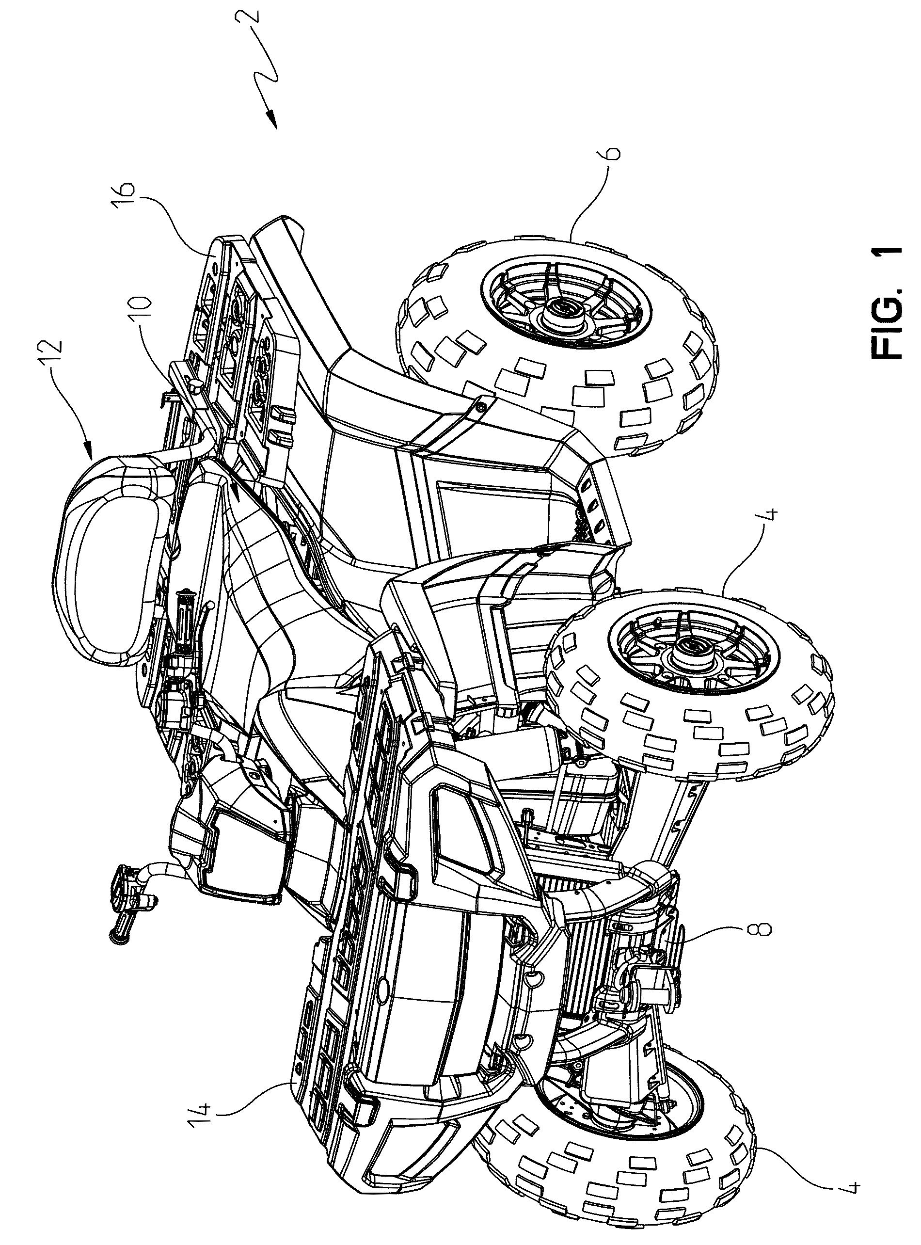
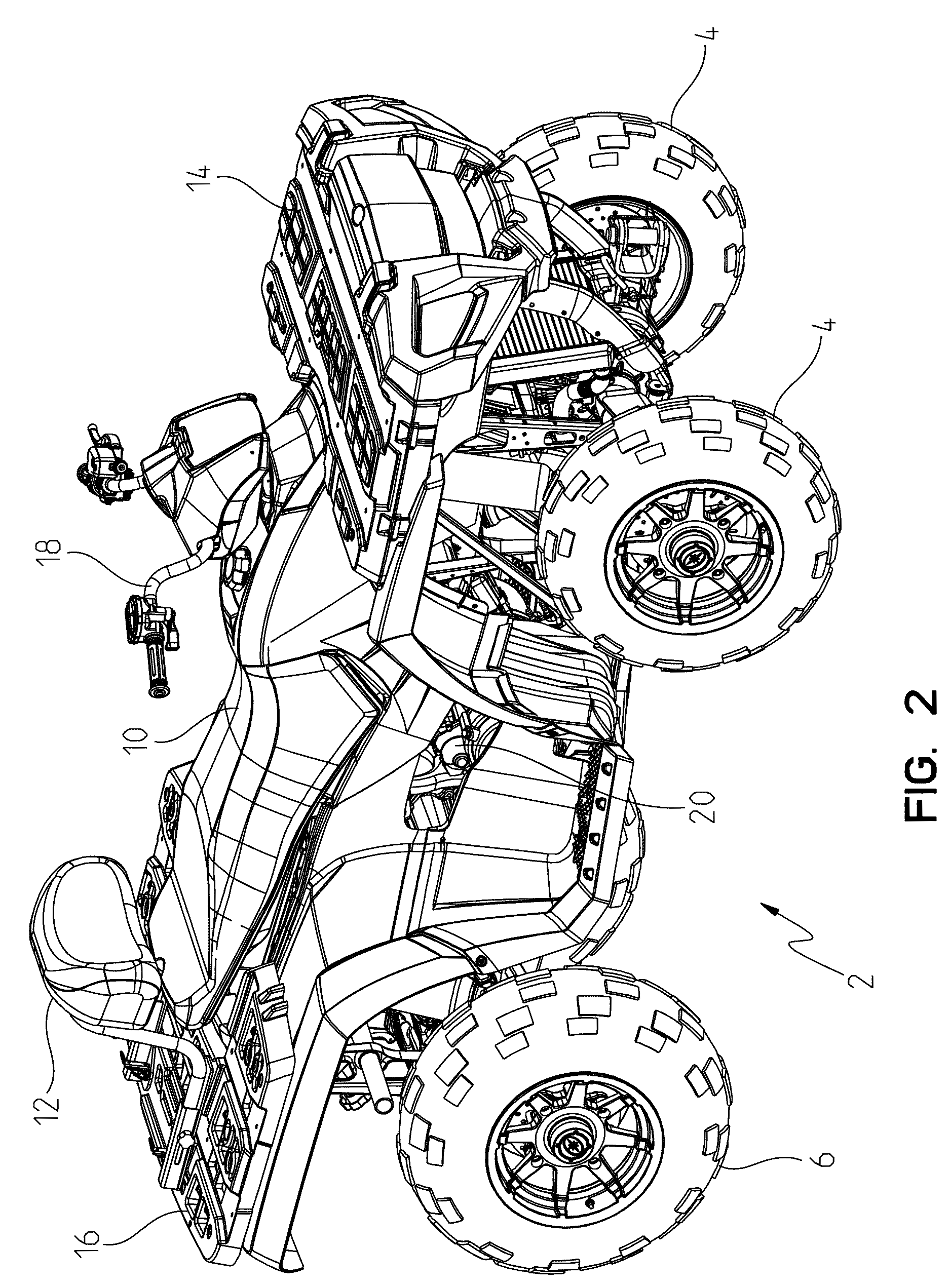
[0038]With reference first to FIGS. 1-3, the tractor is shown generally at 2. The tractor 2 is of the type of a four-wheel drive vehicle having front drive wheels 4, and rear drive wheels 6 which support a frame 8 of the tractor. The tractor 2 also includes a seat 10 for a single rider, having a backrest at 12 with a front utility rack 14 and a rear utility rack 16. The tractor is steerable by way of a steering assembly 18 and is motively projected by way of a drive train at 20 (FIG. 2).

[0039]With reference now to FIGS. 4-8, frame 8 is shown in greater detail. Frame 8 is generally comprised of a longitudinally extending upper frame portion 26 which is generally comprised of longitudinally extending frame members 28 held in a fixed relation by way of a crossbar 30. A lower frame member 32 is rigidly attached to the upper frame member 26 by way of frame uprights 34, 36 and 38. The tractor 2 also includes an enhanced rider area which is comprised of a seat height adjustment assembly sh...


PUM


Abstract

A tractor is disclosed as a four-wheel drive vehicle with a movable seat back, with a seat height adjustment and with a varying load capability.

Description

[0001]This application claims priority from U.S. Provisional application 61 / 135,864 filed Jul. 24, 2008, the subject matter of which is incorporated herein by reference.RELATED APPLICATIONS[0002]This application is related to application Ser. No. 12 / ______ co-filed with the present application and entitled “TRACTOR VEHICLE”, Attorney docket number PLR-02-23282.02P.BACKGROUND OF THE INVENTION[0003]The present disclosure relates to vehicles which may be classified as tractors.[0004]Many different types and styles of vehicles are used for utility purposes, and many different country laws and regulations apply to many applications. Generally, all terrain vehicles (“ATVs”) and utility vehicles (“UVs”) are used to carry one or two passengers and a small amount of cargo over a variety of terrains. Most ATVs include an engine including between one and three cylinders. Generally, the engine is mounted in the frame of the ATV and most ATVs include a straddle or saddle type seat positioned abo...

Claims


Application Information

Patent Timeline
Patent Type & Authority Applications(United States)
IPC IPC(8): B60W30/18B60K13/02
CPCB60N2/10B60N2/0284B60N2/522B60N2/502F02D9/14B60N2/505F02D9/02F02M35/162B60N2/544B60K13/02F02M35/10032F02D2200/501F02D31/006F02D2009/023
Inventor UTKE, JEREMYJUBIE, DAVIDMCKOSLEY, JAYSKIME, TIM
Owner POLARIS IND INC
Why Eureka
Try Eureka