Fuel system for retarded armature lifting speed and fuel system operating method

a technology of fuel system and retarded armature, which is applied in the direction of charge feed system, fuel injection apparatus, electric control, etc., can solve the problems of affecting performance, affecting valve timing, accuracy, or precision, and fuel system components in internal combustion engines are typically complex apparatuses

Active Publication Date: 2022-04-12
CATERPILLAR INC
View PDF5 Cites 1 Cited by
  • Summary
  • Abstract
  • Description
  • Claims
  • Application Information

AI Technical Summary

Benefits of technology

[0007]In still another aspect, a fuel control system includes a fueling control unit having a data processor, and a computer readable memory. The computer readable memory stores fueling control instructions for actuating a fuel injector to inject fuel into a combustion cylinder in an engine. The data processor is structured by way of executing the fueling control instructions to energize a solenoid in the fuel injector with a lift current pulse to lift an armature coupled to a valve pin in an injection control valve assembly, and energize the solenoid with a capture current pulse to capture the armature at a lifted position. The fueling control unit is further structured to deenergize the solenoid for a dwell time while the armature is in flight toward the lifted position, and to retard a lifting speed of the armature based on the deenergizing of the solenoid for a dwell time so as to limit bouncing the valve pin against a stop in the fuel injector.

Problems solved by technology

Fuel systems in internal combustion engines, and notably compression-ignition engines, are typically complex apparatuses.
Fuel injectors and other fuel system components are subjected to harsh service conditions including high fluid pressures and rapid pressure changes, and repeated impacts of valve assembly components over time.
It has been observed that “bouncing” of certain fuel injector components, for instance, where a component such as a valve bounces against a valve seat or stop, can negatively impact performance, particularly with respect to valve timing, accuracy, or precision.
Accordingly, strategies for valve timing accuracy and precision improvements that are successful for one fuel injector configuration may have limited applicability to other designs.

Method used


Image

  • Fuel system for retarded armature lifting speed and fuel system operating method
  • Fuel system for retarded armature lifting speed and fuel system operating method
  • Fuel system for retarded armature lifting speed and fuel system operating method

Examples


Embodiment Construction

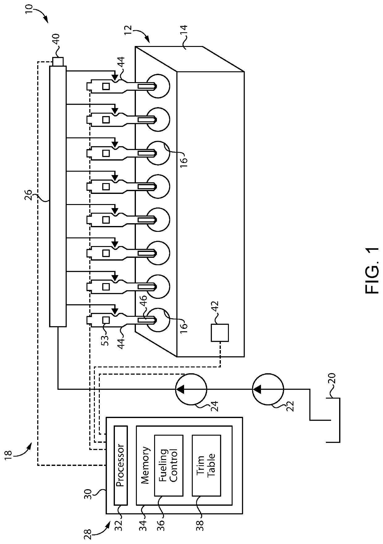
[0014]Referring to FIG. 1, there is shown an internal combustion engine system 10 according to one embodiment. Internal combustion engine system 10 includes an internal combustion engine 12 including an engine housing 14 having a plurality of combustion cylinders 16 formed therein. Combustion cylinders 16 can include any number of combustion cylinders in any suitable arrangement, such as an inline pattern, a V-pattern, or still another. Internal combustion engine system 10 can be employed for propelling a vehicle, powering a pump, a compressor or other industrial equipment, or for generating electrical power, to name a few examples. Each of combustion cylinders 16 will be equipped with a piston, with the pistons coupled to a crankshaft in a generally conventional manner. Internal combustion engine system 10 may also be equipped with an intake system, typically including one or more turbochargers, an exhaust system structured for emissions control, a valve train and various other com...


PUM


Abstract

A fuel system for an internal combustion engine includes a fuel injector, and a fueling control unit electrically connected to a solenoid in the fuel injector. The fueling control unit energizes the solenoid with a lift current pulse to lift an armature, then energizes the solenoid with a separate capture current pulse to capture the armature at a lifted position. The solenoid is deenergized a dwell time while the armature is in flight toward the lifted position. Armature lifting speed is retarded based on the deenergizing of the solenoid so as to limit bouncing of a valve pin in the fuel injector against a stop. The techniques assist in linearizing a fuel delivery curve.

Description

TECHNICAL FIELD[0001]The present disclosure relates generally to a fuel system for an internal combustion engine, and more particularly to energizing a solenoid with multiple current pulses separated by a dwell time so as to retard a control valve armature in a fuel injector.BACKGROUND[0002]Fuel systems in internal combustion engines, and notably compression-ignition engines, are typically complex apparatuses. Fuel injectors and other fuel system components are subjected to harsh service conditions including high fluid pressures and rapid pressure changes, and repeated impacts of valve assembly components over time. Fuel pressures can be in excess of 200 megapascals (MPa), and such injectors will be actuated millions or even billions of times over the course of a service life. Reliable and repeatable performance of fuel injector components, particularly with respect to fuel delivery quantity, can be critical to achieving power density, emissions mitigation, and efficiency goals.[000...

Claims


Application Information

Patent Timeline
Patent Type & Authority Patents(United States)
IPC IPC(8): F02D41/40F02D41/20F02M63/00
CPCF02D41/20F02D41/40F02M63/0021F02D2041/2027F02D2041/2037F02M63/0035F02D41/38F02M47/027F02D2041/2003
Inventor HILL, ADAM CHARLESLI, ZHENYU
Owner CATERPILLAR INC
Why Eureka
Try Eureka