Driving tool
A technology for driving into tools and combustion chambers. It is used in striking tools, manufacturing tools, nailing tools, etc. It can solve problems such as reduced ignition performance, and achieve the effects of reducing burden, preventing poor reset, and suppressing shock and vibration.
- Summary
- Abstract
- Description
- Claims
- Application Information
AI Technical Summary
Problems solved by technology
Method used
Image
Examples
no. 1 approach >
[0054] [Structure example of driving tool 10]
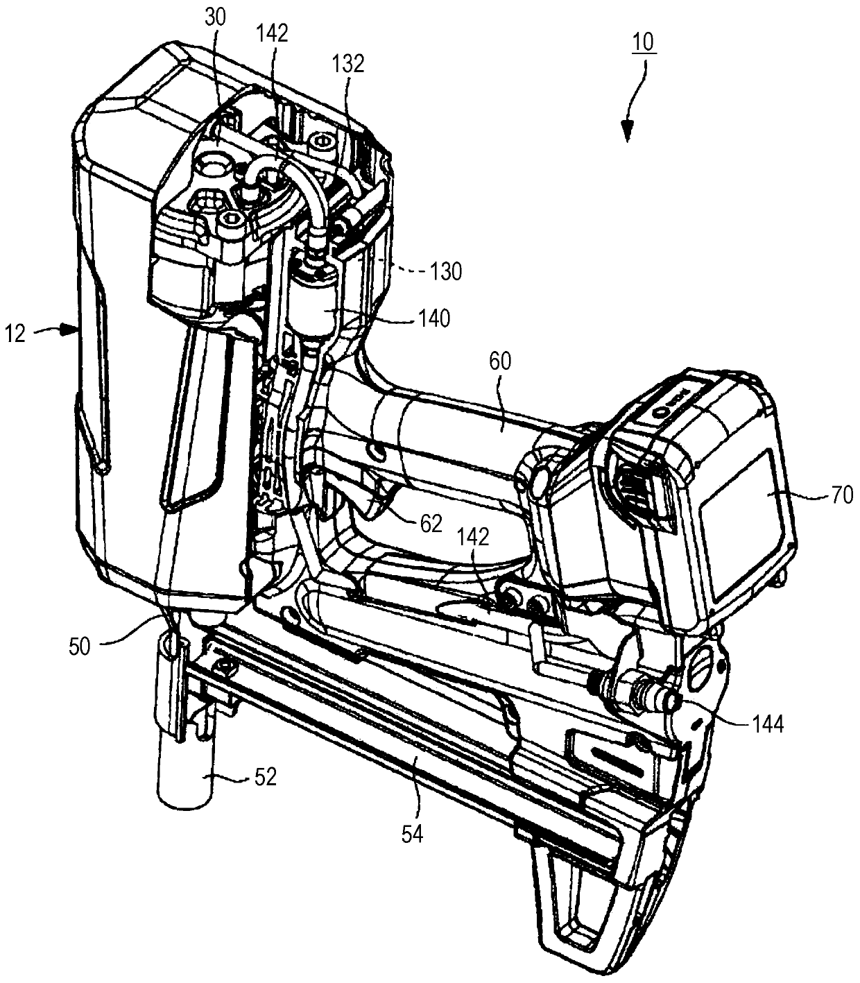
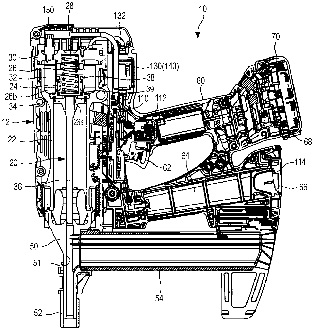
[0055] figure 1 and figure 2An example of the structure of a driving tool 10 according to an embodiment of the present invention is shown. In addition, in figure 1 and figure 2 , set the nail driving direction to the bottom, and the opposite side to the top. In addition, in figure 1 and figure 2 Here, the tool main body 12 side is set to the front, the battery 70 side is set to the rear, the contact arm 52 side is set to the lower side, and the cylinder head 30 side is set to the upper side. In addition, in the direction orthogonal to the front-back direction and the up-down direction of the driving tool 10, the right side when the front direction is taken as a reference is the right side of the driving tool 10, and the left side is the side of the driving tool 10. left side.
[0056] Such as figure 1 and figure 2 As shown, the driving tool 10 is a tool for driving fasteners such as nails, staples, and pins into par...
no. 2 approach >
[0140] In the second embodiment, the scavenging of the driving tool 10 will be described in detail. In addition, since the basic structure and operation of the driving tool 10 are the same as those of the first embodiment, the same reference numerals are attached to the common constituent elements, and detailed descriptions are omitted.
[0141] [Sequence chart at the time of operation of the driving tool 10]
[0142] Figure 8 A timing chart of each device and a graph of pressure fluctuations in the combustion chamber 32 are shown during the driving operation of the driving tool 10 of the present invention. In addition, in the graph, the vertical axis represents pressure and the horizontal axis represents time.
[0143] Such as Figure 8 As shown, at time t1, when the operator presses the contact arm 52 against the component to be driven, the contact arm 52 moves upward relative to the machine head 50, and the contact switch 110 switches from high to low. Ping, the contac...
no. 3 approach >
[0187] In the third embodiment, the operation of the machine is controlled based on the status information of the driving tool 10 . In addition, since the basic structure and operation of the driving tool 10 are the same as those of the first embodiment, the same reference numerals are attached to the common constituent elements, and detailed descriptions are omitted.
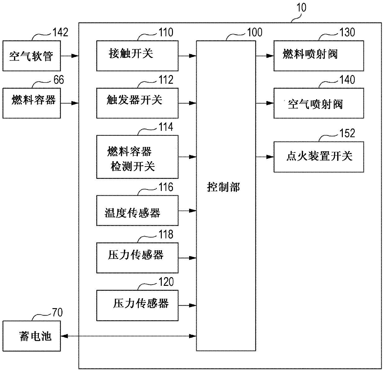
[0188] Figure 12 It is a flowchart showing an example of the operation of the driving tool 10 when it is determined that the machine is abnormal. Such as Figure 12 As shown, in step S500, the temperature sensor 116 detects (acquires) the temperature of the driving mechanism 20 and the like in the tool body 12, and the control unit 100 obtains the temperature of the driving mechanism 20 and the like in the driving tool 10 from the temperature sensor 116 ( Institution Department) temperature information. After step S500 ends, go to step S510.
[0189] In step S510, the control unit 100 determines whether or...
PUM
 Abstract
Description
Claims
Application Information
 - R&D
- Intellectual Property
- Life Sciences
- Materials
- Tech Scout
- Unparalleled Data Quality
- Higher Quality Content
- 60% Fewer Hallucinations
Browse by: Latest US Patents, China's latest patents, Technical Efficacy Thesaurus, Application Domain, Technology Topic, Popular Technical Reports.
© 2025 PatSnap. All rights reserved.Legal|Privacy policy|Modern Slavery Act Transparency Statement|Sitemap|About US| Contact US: help@patsnap.com


