Assembly of a Fixed Pane on a Car Body Flange and Fastening Clip for Mounting of the Fixed Pane

a technology for fixing panes and car bodies, which is applied in the direction of roofs, couplings, transportation and packaging, etc., can solve the problems of unalterable sequence of execution, many manipulation operations or working steps, and the inability to manufacture such a positive engagement, etc., to achieve convenient sliding or placing of fastening clips, reliable sealing, and high tensile strength

Inactive Publication Date:
View PDF23 Cites 11 Cited by
  • Summary
  • Abstract
  • Description
  • Claims
  • Application Information

AI Technical Summary

Benefits of technology

[0017]According to a preferred configuration of the fastening clip, the at least one arm and the at least one locating member are provided with insertion bevels which have opposite directions of action with respect to each other, i.e. which are inclined in opposite directions. This permits to first slide the fastening clip in an easy manner onto the retaining member of the molding and then to perform an insertion movement pushing the fastening clip onto the body flange in an easy manner.
[0018]According to a further preferred configuration of the invention, the sleeve-shaped main body is designed to have at least two preferably mirror-inverted halves, which are connected on the head portion by means of a preferably land-shaped articulation. This configuration makes it possible that the two halves may widen about their articulation, such that during the movement of sliding the fastening clip onto the retaining member a slight expansion of the halves caused by the radially inward-facing locating members occurs. This facilitates the movement of sliding or placing the fastening clip. In addition, an outer circumferential surface of the retaining member is not damaged. Alternatively, four identical body portions may, for example, be provided, so that two opposing articulated portions, respectively, form a common pivot axis along which the halves, or the quarters, may open.
[0019]According to a further preferred configuration of the fastening clip, the locating members are designed to have a bead-like or barb-like cross-section. The bead-like configuration of the locating members causes a diameter reduction of a circumferential surface of the retaining member when the fastening clip is arranged in the insertion through-hole. Thus, a positive engagement or a friction-type engagement between the fastening clip and the retaining member is achieved. In the alternative embodiment, the barb-like locating members are designed to enter in engagement with the retaining member, clutching at an outer circumferential zone of the retaining member. Thus it is possible to achieve a higher tensile force between the fastening clip and the retaining member.
[0020]In another advantageous configuration of the fastening clip, a centering member adjoining the base portion and having an insertion bevel preferably oriented towards the head portion of the main body is preferably designed to be provided between two radially spaced-apart arms arranged on the sleeve-shaped main body. The centering member permits an alignment of the fastening clip and the retaining position of the molding, respectively, in order to achieve a reliable sealing between the pane and the body opening. In addition, this may also provide a uniform alignment of the pane with respect to the body opening. On each half of the main body, a centering member is preferably provided. Due to the clearance provided between the two halves of the main body—with the exception of the land-shaped articulation portion—and due to the at least slightly resilient material of the retaining member, an at least slightly elastically resilient assembly is provided, such that the centering members enable a reliable and positionally correct assembly.
[0021]Preferably in the case of the round, sleeve-shaped main body, the base portion of the fastening clip configured in accordance with the present invention is formed, at least in part, as a circumferential, annular collar which is provided on its outside, with a contact surface for positioning on the molding and is provided, on the opposite side, with a fastening surface facing towards the free end of the arm, with the distance between the fastening surface and the free end of the arm corresponding at least to the thickness of the body flange surrounding the insertion through-hole. Thus, a secure positioning of the fastening clip on the body flange as well as a simple structure of the fastening clip may be realized. The same holds true, by analogy, for the square or rectangular main body, the annular collar being substituted by outward-facing land portions.
[0022]The fastening clip of the present invention is preferably realized as an injection-molded plastic part. This permits a cost-effective fabrication, the configuration of the fastening clip making it possible to use an injection mold consisting of two parts.

Problems solved by technology

This assembly has the disadvantage that several manipulation operations, or working steps, are necessary in order to mount a fixed pane on a body flange.
In addition, this implies an unalterable sequence of execution of the various mounting steps for the vehicle interior during the fabrication process of a vehicle.
The fastening clip used for this assembly has the disadvantage that for one thing it is necessary to provide a specifically configured base portion for forming an ultrasonically welded connection with the molding, and that the fabrication of such a positive engagement is expensive.

Method used


Image

  • Assembly of a Fixed Pane on a Car Body Flange and Fastening Clip for Mounting of the Fixed Pane
  • Assembly of a Fixed Pane on a Car Body Flange and Fastening Clip for Mounting of the Fixed Pane
  • Assembly of a Fixed Pane on a Car Body Flange and Fastening Clip for Mounting of the Fixed Pane

Examples


Embodiment Construction

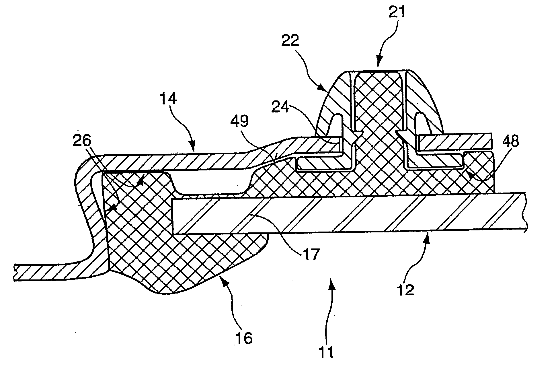
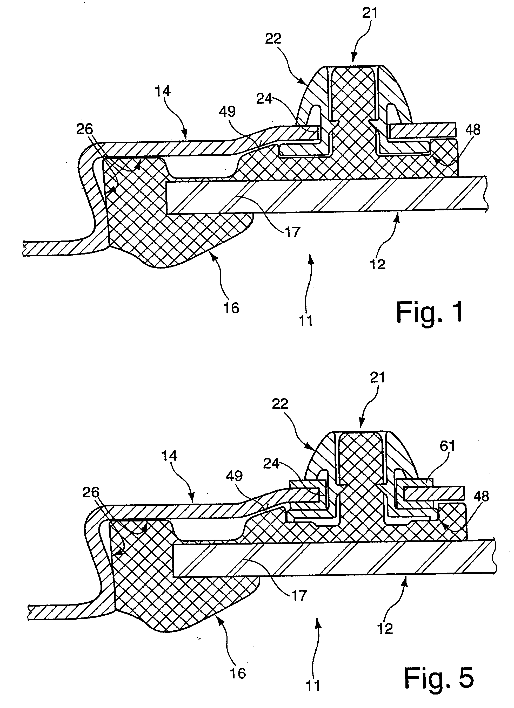
[0030]FIG. 1 represents a schematic sectional view of the assembly 11, according to the invention, of a fixed pane 12 on a body flange 14 surrounding a body opening of a motor vehicle not represented in greater detail. The pane 12 is arranged on the body flange 14 in a sealing and close-fitting manner by means of a molding 16 which surrounds the pane circumferential edge 17 The pane 12 is preferably realized as a glass pane and may be inserted as a side window, a rear window and / or a windshield.

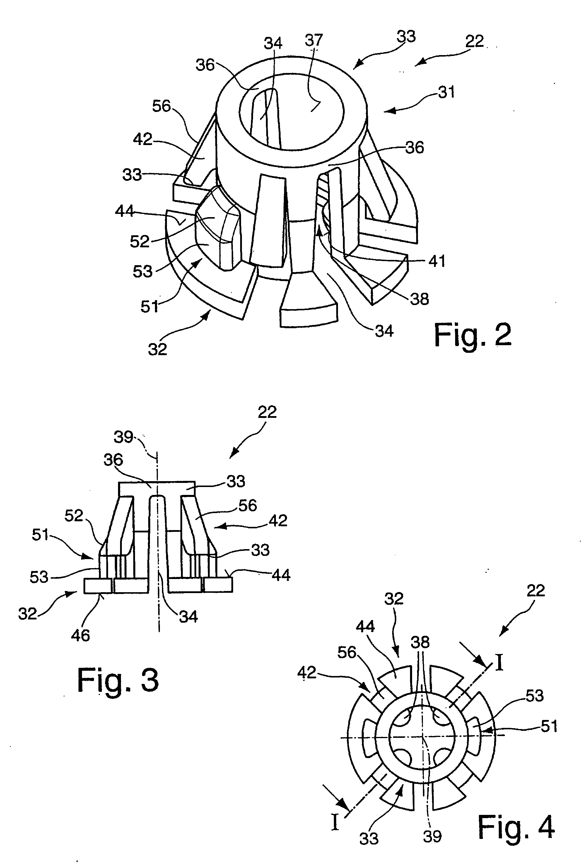
[0031]The molding 16 extending at least on an inner surface of the pane circumferential edge 17 of the pane 12 is provided with a retaining member 21. The retaining member 21 is preferably integrally formed with the molding 16. Alternatively, this retaining member 21 may also be formed separately and may be connected to the molding either by means of a snap-on connection or a clamping connection or by means of a material engagement such as bonding, or welding A fastening clip 22 is slid onto ...


PUM


Abstract

The invention relates to an assembly of a fixed pane on a car body flange and to a fastening clip for mounting the fixed pane which has a molding arranged on the pane circumferential edge and wherein on the molding at least one retaining member facing towards the body flange is provided for accommodating said fastening clip before the fastening clip for mounting the pane to the body flange is fixed in an insertion through-hole of the body flange in an automatically locking manner.

Description

CROSS-REFERENCE TO RELATED APPLICATIONS[0001]The present application claims priority under 35 U.S.C. 119 of German Application No. 10 2008 034 400.1, filed Jul. 23, 2008, which is incorporated herein by reference.BACKGROUND OF THE INVENTION[0002]The invention relates to an assembly of a fixed pane on a car body flange and to a fastening clip for mounting a fixed pane on a body flange.[0003]An assembly relating to a fixed pane on a body flange of a motor vehicle in which the pane is provided with an injection-molded part extending around a circumferential edge of said pane (and referred to hereinafter by the term ‘molding’) is known from DE 33 33 672 A1. At an inner surface of the pane, a fastening clip is provided on the molding and is integrally connected to the molding by ultrasonic welding. This fastening clip may be arranged in an insertion through-hole provided in the body flange. In order to fix the fastening clip, which is realized as an expansion clip, on the body flange, an...

Claims


Application Information

Patent Timeline
Patent Type & Authority Applications(United States)
IPC IPC(8): E06B3/00F16B5/06
CPCY10T403/648B60J1/006F16B2200/509
Inventor BISSINGER, RAINERHERBST, ERICHKNUPFER, GUIDOSCHEUFLER, JOACHIM
Why Eureka
Try Eureka