Subsea well intervention systems and methods

a well-controlled and sub-sea technology, applied in the field of well-controlled and intervention methods and systems, can solve the problems of complicated mechanical properties of sstt and cwor systems, and is not readily availabl

Active Publication Date: 2010-02-04
BP CORP NORTH AMERICA INC
View PDF6 Cites 83 Cited by
  • Summary
  • Abstract
  • Description
  • Claims
  • Application Information

AI Technical Summary

Benefits of technology

[0018]Systems within the present disclosure may take advantage of existing components of an existing BOP stack, such as flexible joints, riser adapter mandrel and flexible hoses including the BOP's hydraulic pumping unit (HPU). Also, the subsea tree's existing Installation WorkOver Control System (IWOCS) umbilical and HPU may be used in conjunction with a subsea control system comprising an umbilical termination assembly (UTA), a ROV panel, accumulators and solenoid valves, acoustic backup subsystems, a subsea emergency disconnect assembly (SEDA), hydraulic / electric flying leads, and the like, or one or more of these components supplied with the system.

Problems solved by technology

SSTT and CWOR systems are complicated mechanically, and not readily available.

Method used


Image

  • Subsea well intervention systems and methods
  • Subsea well intervention systems and methods
  • Subsea well intervention systems and methods

Examples


embodiment 300

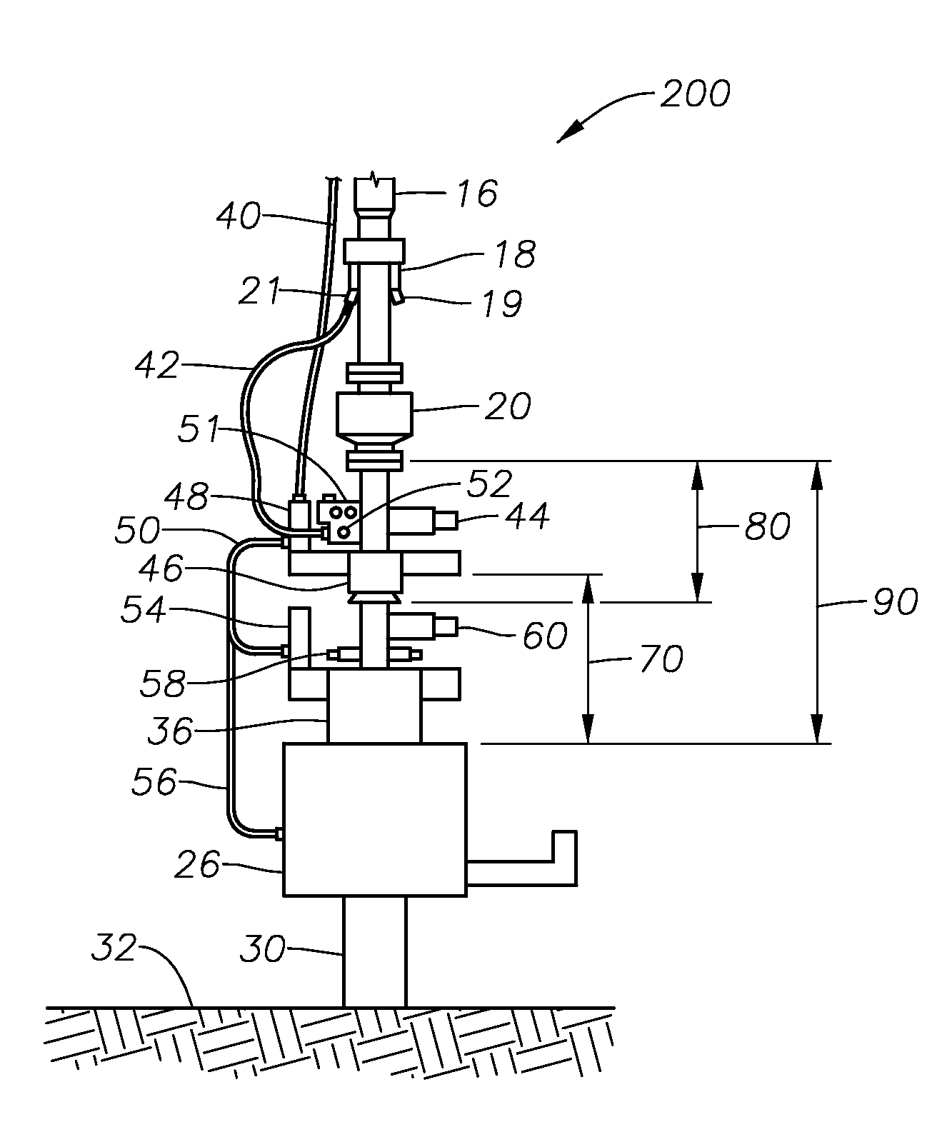
[0065]The LRP 70 includes a body 73, a connector and seal stab adapter (CSSA) 76, and a tree connector 74. Tree connector 74 comprises an upper flange 61a having a gasket profile that mates with CSSA 76 and a lower end 61b for connecting to a subsea tree 26. CSSA 76 comprises at least one seal stab assembly 77 on its lower end for fluidly connecting with subsea tree 26, and an upper flange and gasket profile 79 for mating with the LRP body 73. The body 73 includes a lower sealing ram 58 and a lower isolation valve 60, a lower flange 91 having a profile for matingly connecting with upper flange 79 of CSSA 76, and an upper flange 63 having same profile. The LRP body 73 mates with the EDP body 81 through a quick disconnect connector 88. Embodiment 300 includes a collapse-resistant hose jumper 78 that fluidly connects tree 26 with another gate valve 84 for flow circulation through integral annulus 86, as well as a pressure and temperature measuring unit 82. In an embodiment, the pressur...

embodiment 500

[0089]In the event systems of this disclosure are required to be safely shut-in, this can be initiated from any ESD station, and, depending on the situation, may involve a subsea shut-in and / or emergency disconnect. When a subsea shut-in and emergency disconnect is required, a sequence closure of the shear rams, isolation (gate) valves and connector disconnect will take place. Local hydraulic accumulators are used to assist shear ram closure and connector disconnect. The disconnect time may be less than 45 seconds and the EDP will be automatically picked up vertically since the riser tension will have been previously set to provide sufficient overpull and clearance at the LRP / EDP disconnect point while remaining within the riser's anti-recoil limits. When disconnected, the riser contents may be displaced before the EDP is relanded and connected by the ROV. In certain riserless intervention embodiments, wherein the well intervention operation comprises using a well bore intervention ...


PUM


Abstract

Systems and methods for well intervention include a lower riser package (LRP), and an emergency disconnect package (EDP). The LRP includes a tree connector, a connector and seal stab adapter (CSSA), and a LRP body; the tree connector has a profile for mating to the CSSA. The CSSA has at least one seal stab assembly for fluidly connecting with a subsea tree. The body of the LRP includes one or more sealing elements that are capable of sealing upon command, an integral annulus with an annulus isolation valve, an upper hub profile compatible with the EDP, and a lower flange profile that mates with the CSSA. The EDP includes a quick disconnect connector, at least one annulus isolation valve, and one or more sealing elements that are capable of sealing upon command. In some embodiments, an internal tie-back tool connects to the EDP via an EDP internal tie-back profile.

Description

CROSS-REFERENCE TO RELATED APPLICATIONS [0001]This application claims domestic priority benefit under 35 U.S.C. §120 from applicant's provisional patent application Ser. No. 61 / 085043, filed Jul. 31, 2008, which is fully incorporated herein by reference.BACKGROUND INFORMATION[0002]1. Technical Field[0003]The present disclosure relates in general to well control and intervention methods and systems. More particularly, the present disclosure relates to well control and intervention methods and systems used for well completion, flow testing, well stimulation, well workover, diagnostic well work, bullheading operations, plugging wells and / or abandoning wells, where subsea trees or wellheads are installed. In an embodiment, these systems and methods are deployed using a slickline, e-line, coiled tubing or jointed tubulars, for example.[0004]2. Background Art[0005]The Current practice for well control and intervention for wells completed with horizontal subsea trees is to use a Subsea Tes...

Claims


Application Information

Patent Timeline
Patent Type & Authority Applications(United States)
IPC IPC(8): E21B43/36E21B43/01
CPCE21B33/076E21B33/035
Inventor MCKAY, THOMAS KEANBEDNARZ, MICHAEL J.
Owner BP CORP NORTH AMERICA INC
Why Eureka
Try Eureka