Miniature switch

a technology of miniature switches and switches, applied in the direction of switches with three operating positions, switches with two operating positions, contact mechanisms, etc., can solve the problem of impossible operation of the operating button other than swinging operation

Active Publication Date: 2010-02-04
NKK SWITCHES
View PDF4 Cites 5 Cited by
  • Summary
  • Abstract
  • Description
  • Claims
  • Application Information

AI Technical Summary

Problems solved by technology

Since an operating stroke is short due to the short distance between the spindle and a pressing position, a switching mechanism has been limited to a seesaw type, and other types have not been available.
Further, since both of the above-described switches have the spindle, the operation of the operational button other than the swinging operation has been impossible.

Method used


Image

  • Miniature switch
  • Miniature switch
  • Miniature switch

Examples


first embodiment

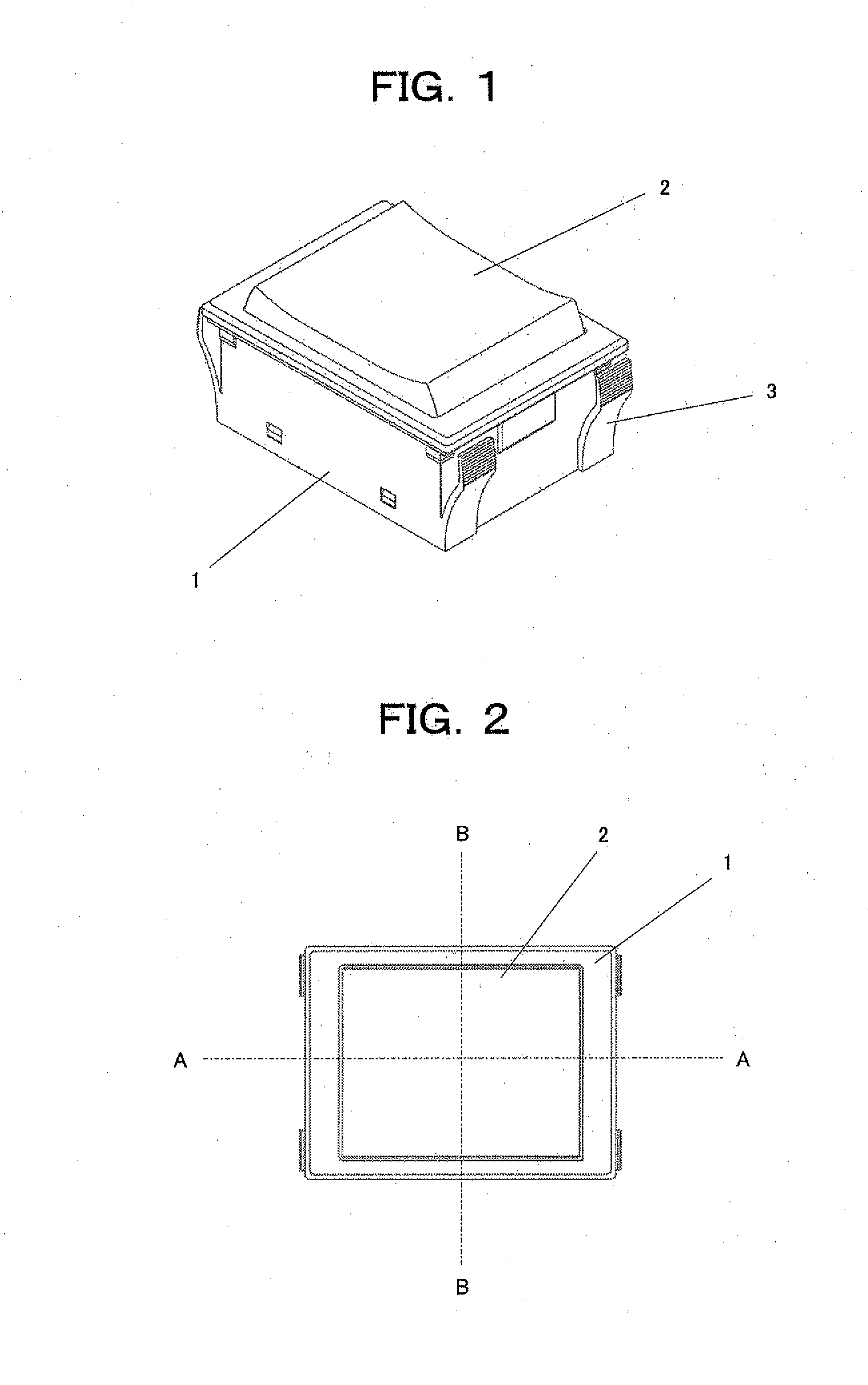
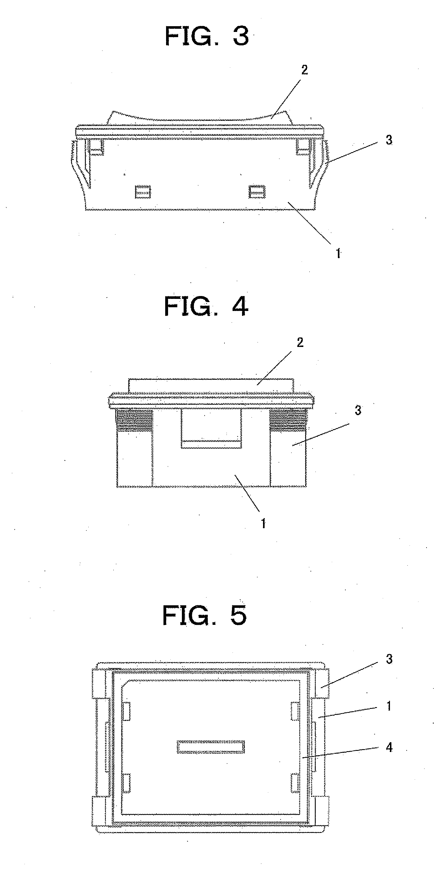
[0040]FIG. 1 is a perspective view of a miniature switch illustrating the present invention, FIG. 2 is a plan view thereof, FIG. 3 is a front view thereof, FIG. 4 is a side view thereof, and FIG. 5 is a bottom view thereof.

[0041]In these figures, reference numeral 1 denotes a housing, 2 an operational button, 3 a leaf spring for fixing the switch, and 4 a case arranged below the housing 1.

[0042]Now, the structure of the miniature switch according to the first embodiment of the present invention will be described.

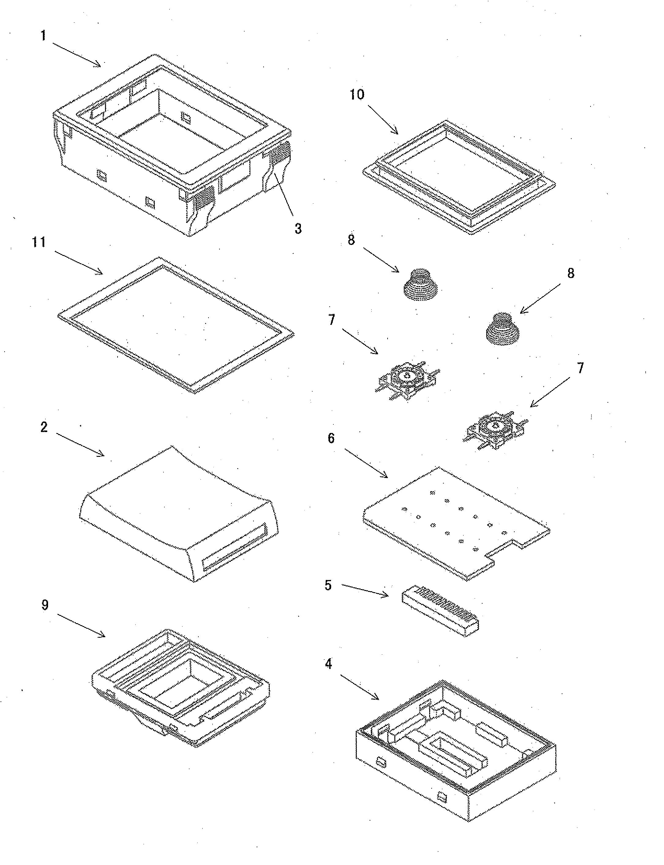
[0043]FIG. 6 is an exploded perspective view of the miniature switch illustrating the first embodiment of the present invention, FIG. 7 is a cross-sectional view taken along the line A-A in FIG. 2, FIG. 8 is a cross-sectional view taken along the line B-B in FIG. 2, and FIG. 9 is a cross-sectional view of the miniature switch in the operating state.

[0044]In these figures, the case 4 is arranged below the housing 1 and accommodates a printed circuit board 6 having a connector...

second embodiment

[0050]Next, the present invention will be described.

[0051]The miniature switch according to the second embodiment is similar in appearance to that of the first embodiment shown in FIGS. 1 to 5.

[0052]FIG. 10 is an exploded perspective view of the miniature switch illustrating the second embodiment of the present invention, FIG. 11 is a cross-sectional view thereof taken along the line A-A in FIG. 2, FIG. 12 is a cross-sectional view thereof taken along the line B-B in FIG. 2, and FIG. 13 is a cross-sectional view thereof in the operating state.

[0053]In these figures, reference numeral 21 denotes a housing, 22 an operational button, 22A a bottom protrusion of the operational button 22, 22B an inner bottom end of the operational button 22, 22C a display window, 23 an organic light-emitting display device (OLED) module, 24 a third packing, 25 a holder, 26 a first packing, 27 a printed circuit board, 28A and 28B left and right switch elements, respectively, 28C a central switch element, ...


PUM


Abstract

A miniature switch with a switch operating unit having a swinging motion about a fulcrum on the side opposing the pressed side, instead of a spindle in the switch operating unit. The miniature switch includes: a switch operating unit composed of a holder 9 and an operational button 2 fixed to the holder 9; and a switch mechanism unit composed of a printed circuit board 6, a connector 5, and switch elements 7 arranged in a case 4, and coil springs 8 which engage between the switch elements 7 and the holder 9, wherein the switch operating unit and the switch mechanism unit are coupled to each other by a first packing 10 made of a resilient material, and the switch mechanism unit and the switch operating unit are disposed in a housing 1.

Description

BACKGROUND OF THE INVENTION[0001]1. Field of the Invention[0002]The present invention relates to a miniature switch, in particular, the miniature switch capable of performing at least a swinging motion, in which the swinging motion of a switch operating unit can be performed using the side opposing the pressed side as a fulcrum instead of providing a spindle in the switch operating unit.[0003]2. Description of the Related Art[0004]The conventional rocker switch which performs swinging operation is provided with a spindle in the central portion of a switch operating unit for allowing a swinging motion, so that the switch operating unit swings about the spindle (Patent Documents 1 to 3 listed below).[0005][Patent Document 1] Japanese Utility Model Application Publication No. 64-033133[0006][Patent Document 2] Japanese Utility Model Application Publication No. 63-137425[0007][Patent Document 3] Japanese Utility Model Application Publication No. 63-006640[0008]As described above, the ro...

Claims


Application Information

Patent Timeline
Patent Type & Authority Applications(United States)
IPC IPC(8): H01H23/08H01H23/24
CPCH01H9/181H01H23/025H01H2219/037H01H23/145H01H23/30H01H23/06
Inventor SAITO, AKIRA
Owner NKK SWITCHES
Why Eureka
Try Eureka