
Electric machine

a technology of electric machines and winding materials, which is applied in the direction of dynamo-electric machines, electrical equipment, magnetic circuit shapes/forms/construction, etc., can solve the problems of high cost of winding materials, and high cost of electrically conductive materials

Active Publication Date: 2010-02-04
NIDEC MOTOR CORP
View PDF32 Cites 18 Cited by
  • Summary
  • Abstract
  • Description
  • Claims
  • Application Information

AI Technical Summary

Benefits of technology

[0004]In some embodiments, the present invention relates to a stator assembly adapted for use in an electric motor. The assembly comprises a stator core having an annular rim and a plurality of teeth extending radially inward from the rim. The core has an outer diameter, a root tooth diameter and an inner diameter. Each tooth of the plurality of teeth has a root, a neck extending inward from the root, a head opposite the root, and a length measured from its root to its head. The neck has a width. Each adjacent pair of teeth of the plurality of teeth defines a slot having an area. Further, the assembly includes a winding comprising at lea

Problems solved by technology

The size, performance and cost of the electric machine frequently have a significant impact on the overall size and cost of the apparatus.
At times, some winding materials are more expensive than others.
For example, sometimes copper is very expensive relative to other electrically conductive materials such as aluminum.
However, larger windings raise concerns about machine size and resulting apparatus size.
But if the exterior size of the motor is restricted by the application in which the motor is to be used, these increases in length and / or diameter cannot be accomplished and the alternative winding material (e.g., aluminum) cannot be used without sacrificing performance.

Method used


Image

  • Electric machine
  • Electric machine
  • Electric machine

Examples


Embodiment Construction

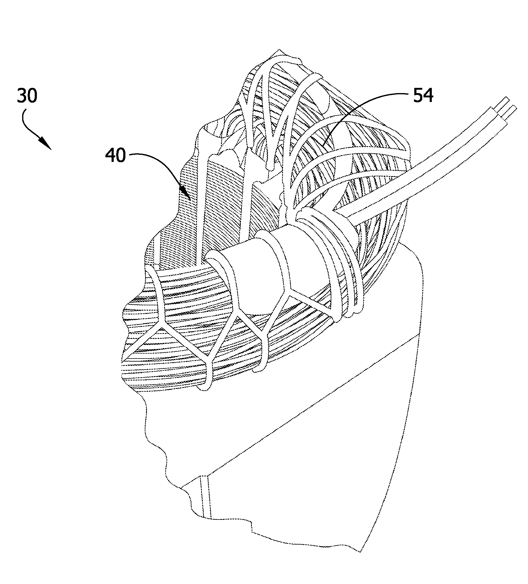
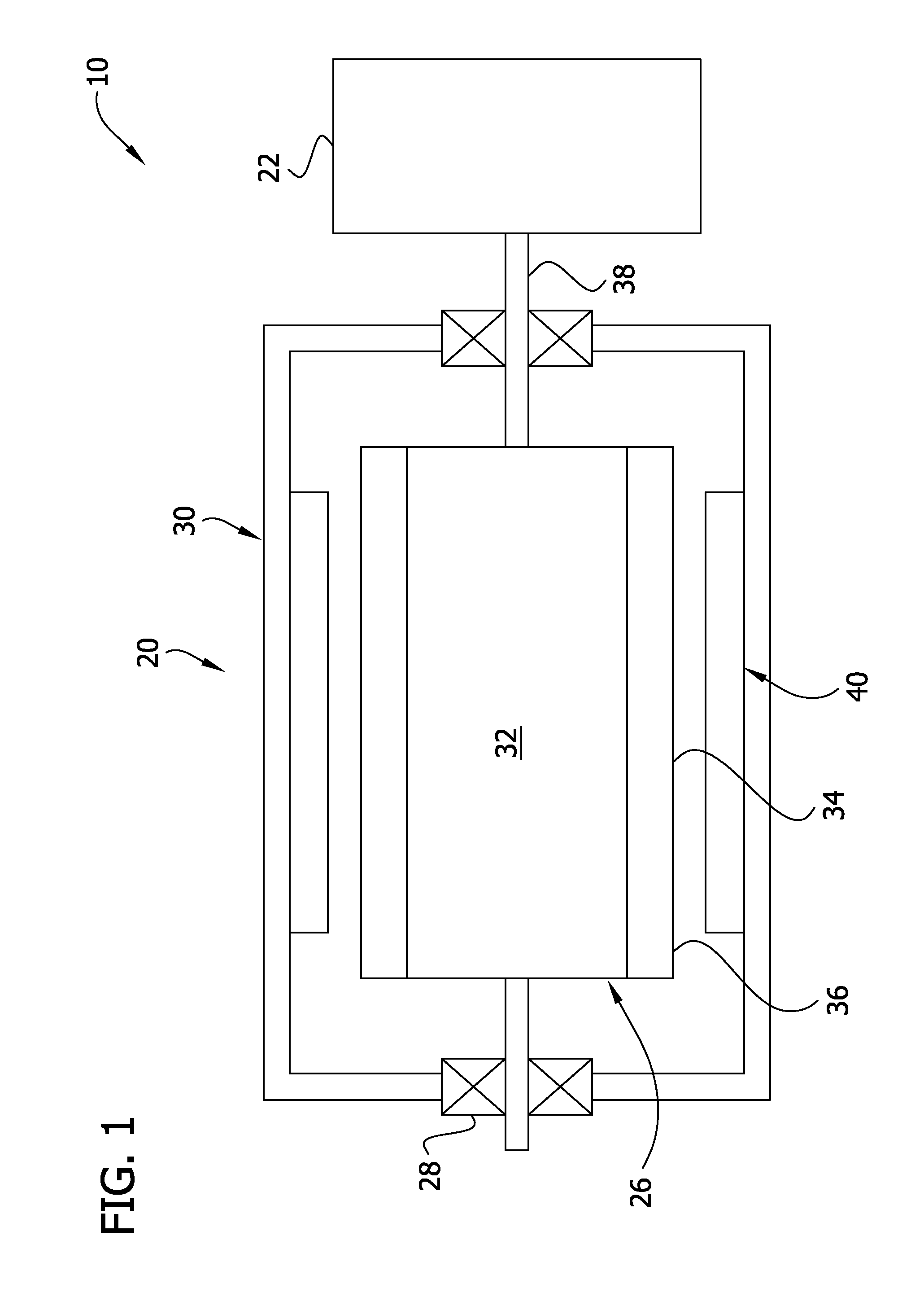
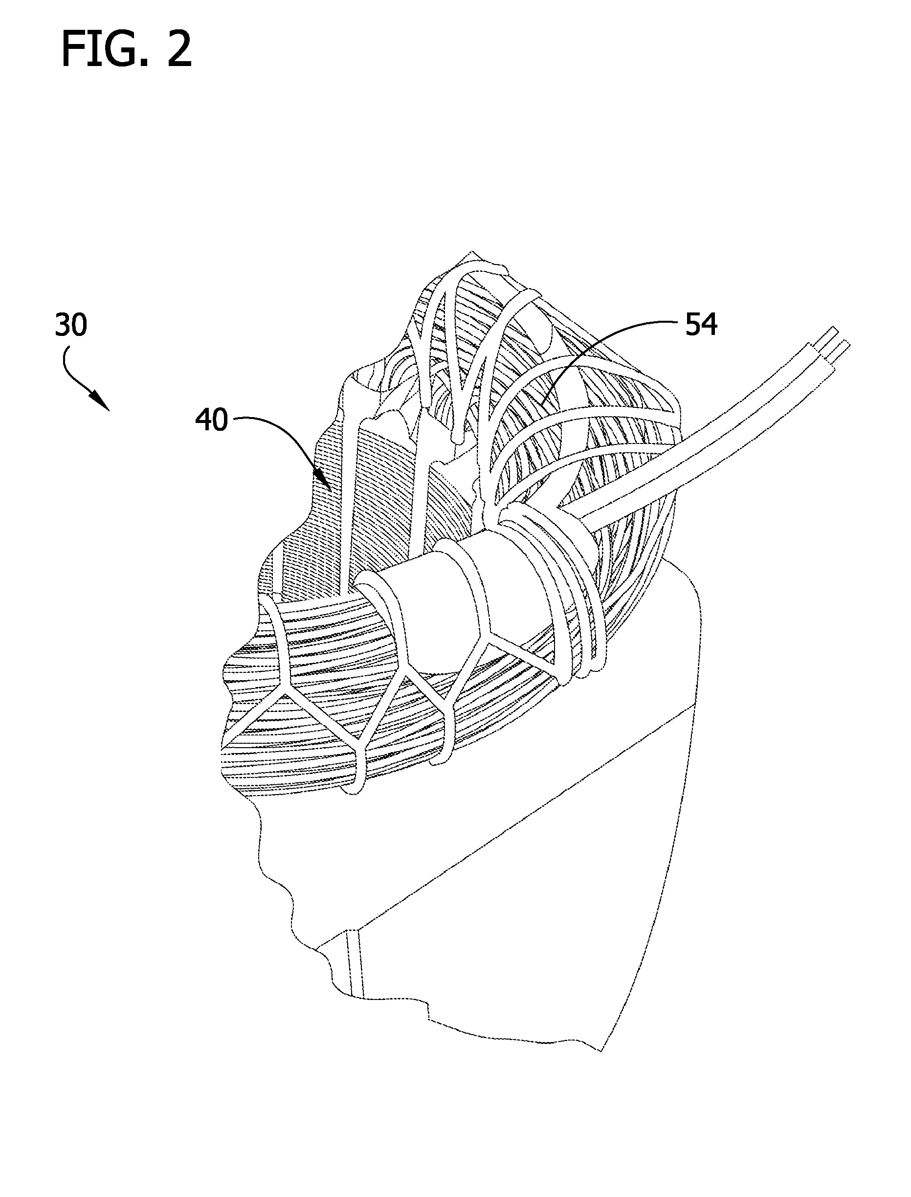
[0019]Referring now to the drawings and in particular FIG. 1, an electric apparatus is designated in its entirety by the reference number 10. In one embodiment, the apparatus 10 comprises an electric motor, generally designated by 20, for driving a device 22. Although the device 22 may be of other types without departing from the scope of the present invention, in some embodiments the device comprises a blower, an impeller, a pulley, a gear, a pump and / or a fan. Further, in some embodiments, the motor 20 has a continuous duty shaft output power of less than about 1 kilowatt. In some embodiments, the motor 20 has a continuous duty shaft output power of less than about 700 watts. The electric motor 20 includes a rotor assembly, generally designated by 26, rotatably supported by bearings 28 mounted in a stator assembly, generally designated by 30. The rotor assembly 26 includes a rotor body 32 having induction rotor bars 34 angularly distributed adjacent an external surface 36 of the r...


PUM


Abstract

A stator assembly adapted for use in an electric motor. The assembly includes a stator core having an annular rim and a plurality of teeth extending radially inward from the rim. The stator core has an outer diameter, a root tooth diameter and an inner diameter. Each tooth has a root, a neck extending inward from the root, a head opposite the root, and a length measured from its root to its head. The neck has a width. Each adjacent pair of teeth define a slot having an area. The assembly also includes a winding having aluminum and / or copper wrapped around at least three teeth of the stator core. The stator core and winding have four, six or eight magnetic dipoles. The stator core outer diameter is in a range from about 5.1 inches to about 5.9 inches. The stator core inner diameter is less than about 3.0 inches.

Description

BACKGROUND[0001]The present invention relates to electric machines, such as motors or generators, and more particularly to electric machines having aluminum windings.[0002]Electric machines, such as motors or generators, typically include a stator mounted inside a housing and a rotor supported in the housing for rotation relative to the stator. The stator and / or the rotor of the machines have windings comprising coils of wire. In motors, electricity is delivered through these coils to generate magnetic fields, causing the rotor to turn. In generators, the electricity is generated in the windings as the rotor turns. Although different electrically conductive materials may be used to make the windings, in the past these windings have frequently been made from copper or copper alloys. Electric machines are often integrated into apparatus such as air handling equipment, washing machines, stationary bicycles and treadmills. The size, performance and cost of the apparatus incorporating th...

Claims


Application Information

Patent Timeline
IPC IPC(8): H02K1/16
CPCH02K3/02H02K1/16
Inventor HUSSEY, JOHN H.CRAPO, ALAN D.BOURQUIN, THOMAS M.
Owner NIDEC MOTOR CORP
Learn More