
Automatic position restoring slide rail device

Active Publication Date: 2010-02-04
NAN JUEN INT CO LTD
View PDF5 Cites 39 Cited by
  • Summary
  • Abstract
  • Description
  • Claims
  • Application Information

AI Technical Summary

Benefits of technology

[0006]Therefore, it is a primary objective of the present invention to provide an automatic position restoring slide rail device with smoother and better automatic position restoration, and the operation will not cause a failure easily and the invention comes with an easy-to-assemble feature, so as to improve the manufacturing cost and the cost-effectiveness for better practicability and competitiveness of the product.

Problems solved by technology

Although the aforementioned prior art can achieve the automatic position restoring function of the drawer, the resilient element is connected to the passive slide element, and the shock absorbing device for reducing shocks is also connected and operated actively with the passive slide element, and thus the resilient restoring function is weakened substantially, and the hydraulic cylinder type shock absorbing device is extended / contracted and operated at the passive slide element, and thus the shock absorbing device is worn out and damaged easily, and the shock absorbing device may cause a failure easily, so as to affect the life expectancy of the overall shock absorbing function adversely.
Obviously, the foregoing prior art is not a good design.
Due to the resilience and the shock absorbing force are the key points of the design of automatic position restoring drawers of this sort, the present technology uses a larger resilience to work with a passive shock absorbing structure to achieve the design, but such prior art is not applicable for the application of this structure, and also requires further improvements.

Method used


Image

  • Automatic position restoring slide rail device
  • Automatic position restoring slide rail device
  • Automatic position restoring slide rail device

Examples


Embodiment Construction

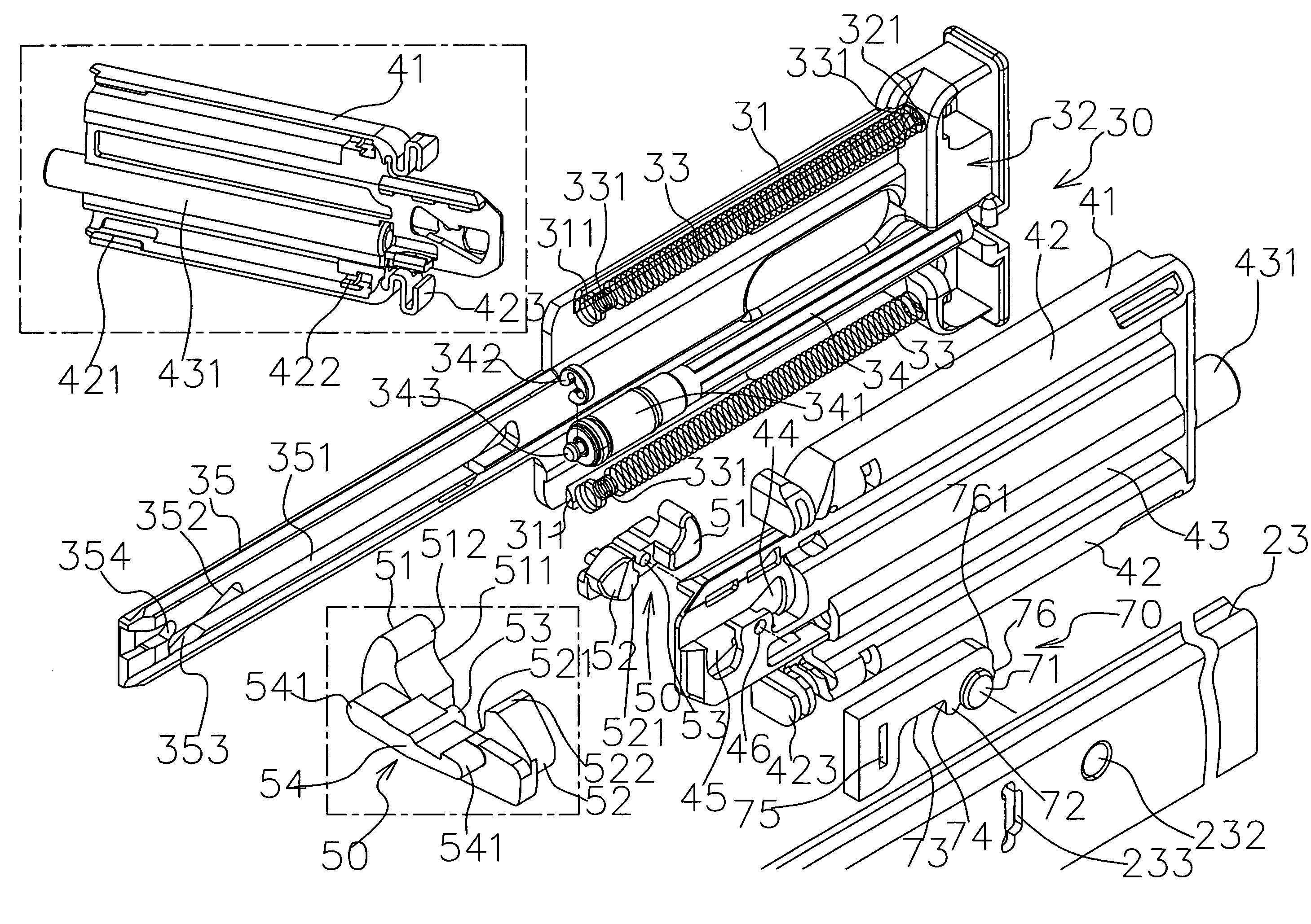
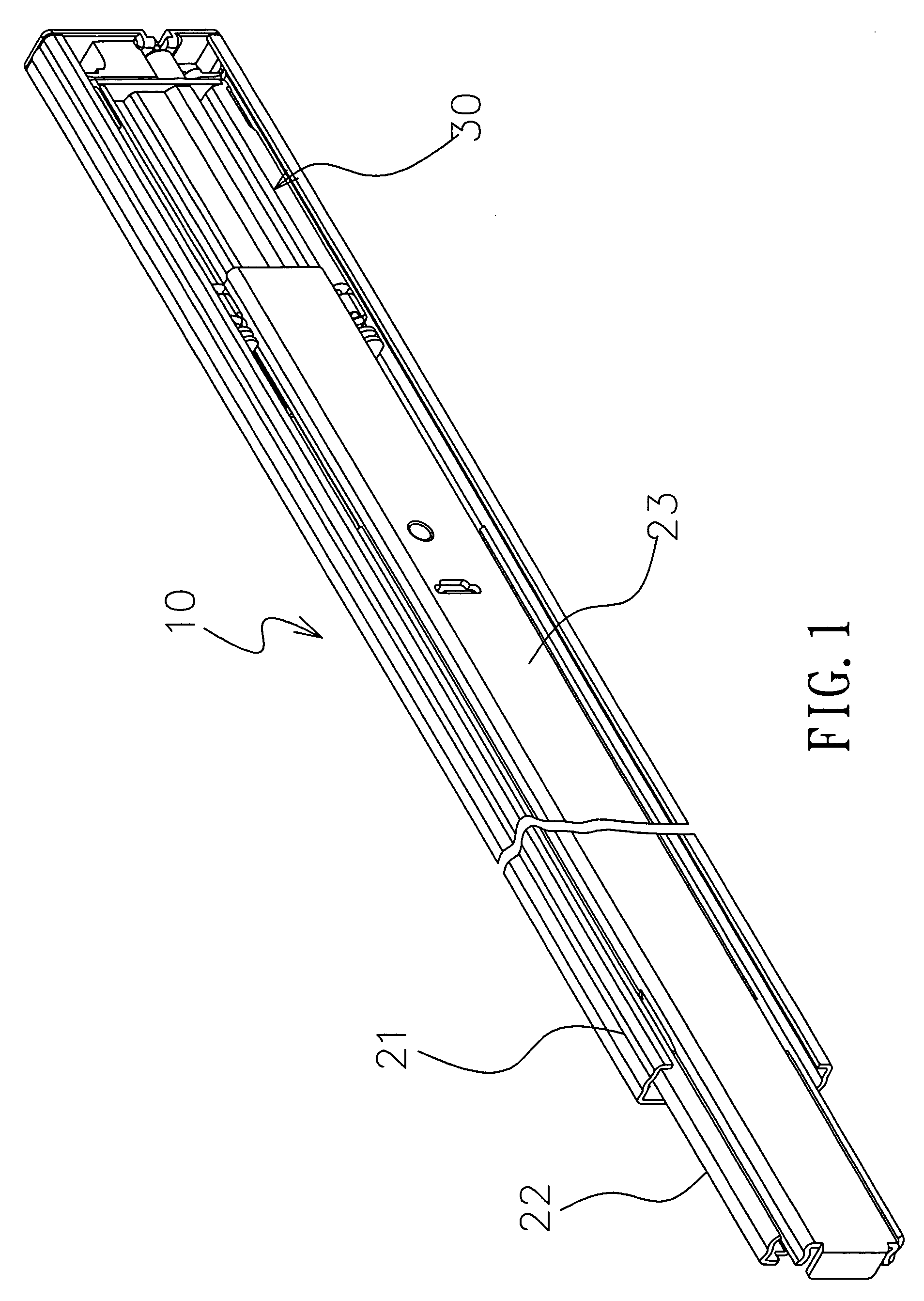
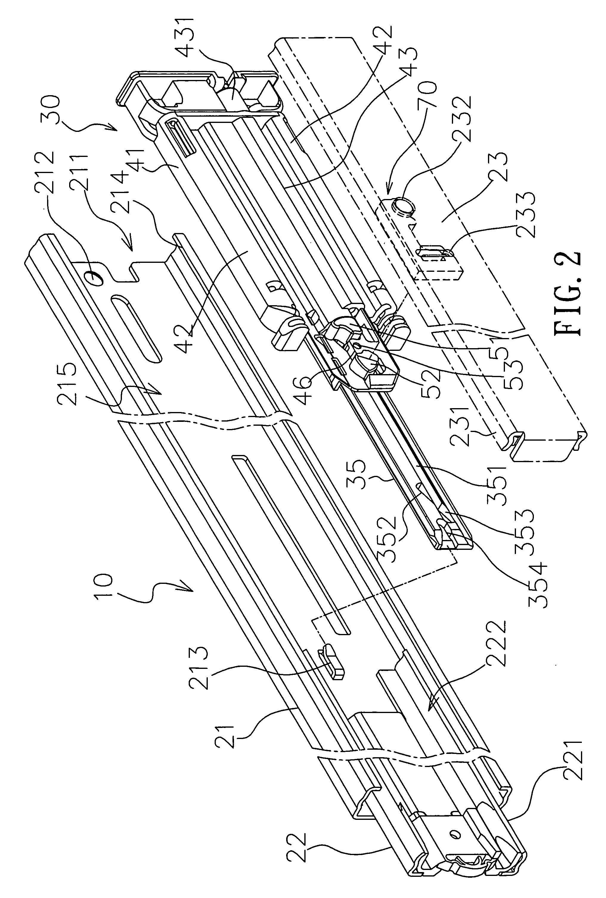
[0021]With reference to FIGS. 1 to 3 for an automatic position restoring slide rail device of the present invention, the automatic position restoring slide rail device comprises a slide rail device 10, a control device 30, a swing element 50 and a link element 70. The slide rail device 10 comprises a bottom rail 21, a middle rail 22 and inner rail 23, wherein the bottom rail 21 is fixed onto a cabinet (not shown in the figure), and the bottom rail 21 has a front end head portion 211 with a fixing hole 212 disposed at the front end head portion 211, and a positioning element 213 disposed at an appropriate position of the bottom rail 21, and a lateral protruding end 214 protruded separately from both sides of the bottom rail 21 for forming a bottom rail space 215, and the middle rail 22 is embedded and slid in the bottom rail space 215 of the bottom rail 21, and the middle rail 22 has a lateral protruding end 221 protruded separately from both sides for forming a middle rail space 222...


PUM


Abstract

An automatic position restoring slide rail device includes: a slide rail device having a bottom rail and an inner rail slid with respect to the bottom rail; a control device having a control base, a spring connected between the control base and the slide cover, and a control plate with a concave guide slot, and the guide slot having a latch groove on one side and an aslant guide slot on another side, and the slide cover being covered at the control base, and having a first return slot and a second return slot; a swing element, including a first actuating block at the first return slot and a second actuating block at the second return slot, a link element, fixed at the inner rail. Therefore, the present invention can achieve a smoother and better automatic position restoration.

Description

BACKGROUND OF THE INVENTION[0001]1. Field of the Invention[0002]The present invention generally relates to a slide rail device, and more particularly to an automatic position restoring slide rail device having the features of a simple structure, easy-to-manufacture and easy-to-assemble features, and a good operability to meet the cost-effective requirement of its manufacture and application.[0003]2. Description of the Related Art[0004]Pull cabinets or drawers are used extensively for containing and storing things or tools, and thus slide rails are generally installed on both sides of the cabinets or drawers to facilitate a stable operation of opening or closing operations of pulling, sliding or positioning the cabinets or drawers. To make it easier and more convenient for users to push and close the cabinets or drawers, the slide rails further integrate an automatic position restoring mechanism, such that if a user pushes the cabinet or drawer to an end section, the automatic positi...

Claims


Application Information

Patent Timeline
IPC IPC(8): A47B88/12
CPCA47B88/0477A47B88/047A47B88/463A47B88/467
Inventor HUANG, KUO-SHENG
Owner NAN JUEN INT CO LTD
Learn More