Method of manufacturing a heat conducting structure having a coplanar heated portion

a heat conducting structure and coplanar heating technology, applied in the direction of tubular elements, indirect heat exchangers, light and heating apparatus, etc., can solve the problems of reducing the heat conduction rate, and reducing the overall weight of the heat sink, so as to reduce the overall weight and manufacturing cost of the heat sink. , the effect of reducing the heat conduction path

Inactive Publication Date: 2013-07-16
CPUMATE INC +1
View PDF15 Cites 1 Cited by
  • Summary
  • Abstract
  • Description
  • Claims
  • Application Information

AI Technical Summary

Benefits of technology

The present invention provides a heat conducting structure with a coplanar heated portion that reduces the overall weight and heat conduction path, thus lowering the manufacturing cost of a heat sink and improving heat dissipating efficiency. Compared to prior art, the invention eliminates the need for a heat conducting base, reducing the heat conduction path and improving heat conduction rate. As a result, the invention is lighter and more practical, with improved cost-effectiveness.

Problems solved by technology

However, the heat conducting base 20a not just increases the overall weight of the heat sink 1a only, but also extends the heat conduction path and retards the heat dissipation rate.
Furthermore, the installation of the heat conducting base 20a also incurs a higher manufacturing cost of the heat sink 1a.

Method used


Image

  • Method of manufacturing a heat conducting structure having a coplanar heated portion
  • Method of manufacturing a heat conducting structure having a coplanar heated portion
  • Method of manufacturing a heat conducting structure having a coplanar heated portion

Examples


Embodiment Construction

[0029]The technical characteristics, features and advantages of the present invention will become apparent in the following detailed description of the preferred embodiments with reference to the accompanying drawings. The drawings are provided for reference and illustration only, but not intended for limiting the present invention.

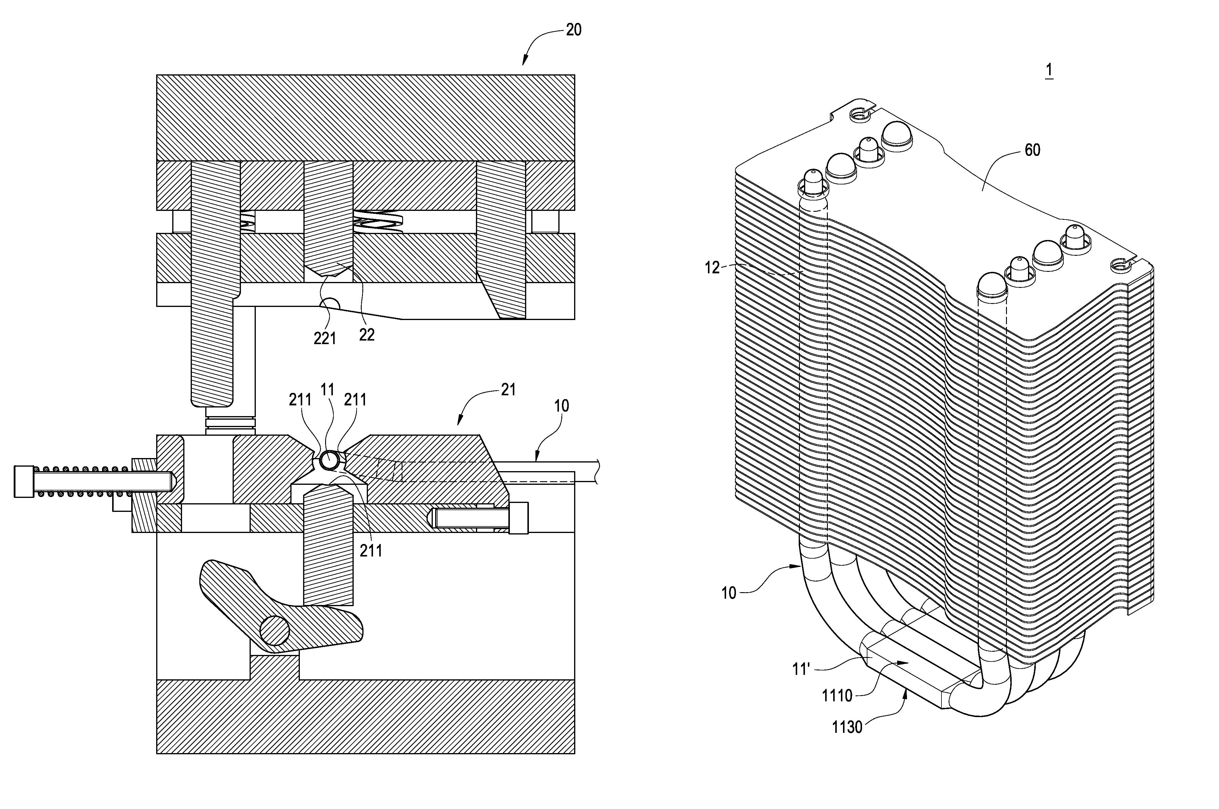
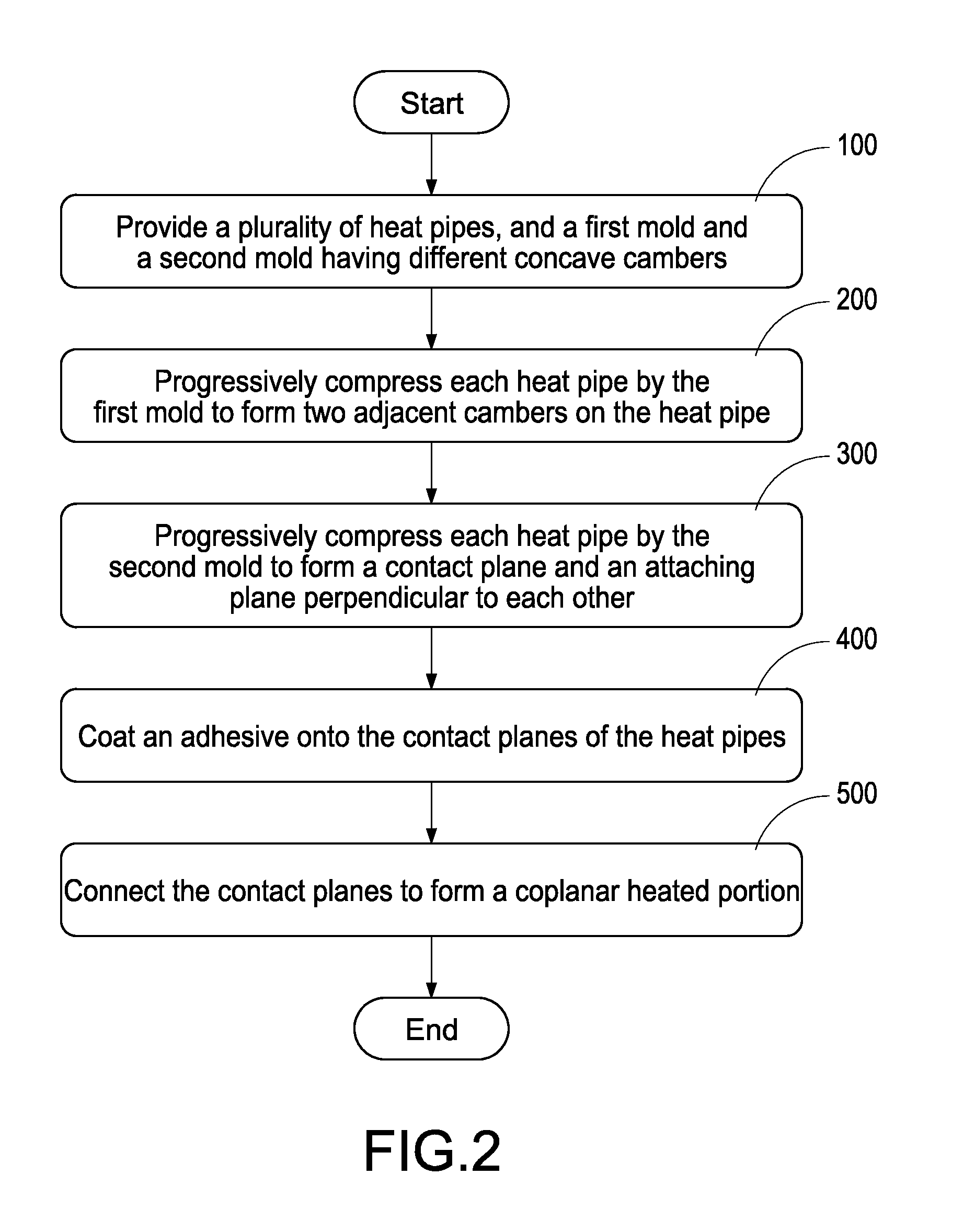
[0030]With reference to FIGS. 2 to 8 for flow charts and schematic views of manufacturing a heat conducting structure with a coplanar heated portion in accordance with the present invention, a plurality of heat pipes 10, a first mold 20 and a second mold 30 are provided first (Step 100). The heat pipe 10 is U-shaped and includes an evaporating section 11 and two condensing sections 12, and the first mold 20 includes a first platform 21 and a first compression rod 22, wherein the first platform 21 of the first mold 20 can have different concave cambers 211, 211a, or a plurality of first molds 20 are used, and the different concave cambers 211, 211a are for...


PUM

PropertyMeasurementUnit
heataaaaaaaaaa
temperatureaaaaaaaaaa
conductingaaaaaaaaaa

Abstract

A heat conducting structure, a heat sink with the heat conducting structure, and a manufacturing method of the heat conducting structure are disclosed. The manufacturing method includes the steps of providing a first mold (20) and a second mold (30) having different concave cambers (211, 211a, 221, 221a), using the first mold (20) to progressively compress the heat pipes (10) and form a camber (112) at an evaporating section (11), using the second mold (30) to compress the camber (112) to form a contact plane (112′) and an attaching plane (113′) perpendicular to each other, coating an adhesive (50) on the contact planes (112′), connecting the contact planes to make the attaching planes co-planar.

Description

BACKGROUND OF THE INVENTION[0001]1. Field of the Invention[0002]The present invention relates to a heat conducting structure, and more particularly to a heat conducting structure having a heat pipe, and a manufacturing method of the heat conducting structure.[0003]2. Description of Prior Art[0004]In general, an electronic component generates heat during its operation. As science and technology advance, the functions and performance of electronic products are enhanced, and the heat generated by the electronic products becomes increasingly larger, so that most electronic components need a heat dissipating device for controlling a working temperature to maintain normal operations of electronic components. For example, a heat pipe filled with a working fluid for conducting heat is one of the common heat conducting devices.[0005]With reference to FIG. 1 for a conventional heat sink, the heat conducting structure 1a of the heat sink 10 comprises a heat conducting base 10a and a plurality ...

Claims


Application Information

Patent Timeline
Patent Type & Authority Patents(United States)
IPC IPC(8): B21D53/06B21D22/06
CPCB21D22/025B21D22/06B21D53/08F28D15/0266F28D15/0275F28D15/043F28F1/32Y10T29/49353Y10T29/53122Y10T29/49391Y10T29/4935F28D15/0233
Inventor LIN, KUO-LENLIN, CHEN-HSIANGHSU, KENCHENG, CHIH-HUNG
Owner CPUMATE INC
Why Eureka
Try Eureka