Heat dissipation structure of LED light

a technology of heat dissipation structure and led light, which is applied in the direction of discharge tube main electrodes, lighting and heating apparatus, semiconductor devices for light sources, etc., can solve the problems of high-temperature components on the led substrate module that often overheat and accelerate the luminous decay of led light, and achieve high heat dissipation efficiency

Inactive Publication Date: 2010-02-04
WU YA LI
View PDF1 Cites 73 Cited by
  • Summary
  • Abstract
  • Description
  • Claims
  • Application Information

AI Technical Summary

Benefits of technology

[0007]It is therefore a primary object of the present invention to provide an LED light with high heat dissipation efficiency. The LED light includes an LED substrate module, a ventilation power supply seat module, a ventilation lampshade and an annular thermal module. The annular thermal module is composed of multiple streamlined curved-surface radiating fins stacked in an annular pattern.

Problems solved by technology

As a result, the high-temperature components on the LED substrate module often overheat to accelerate luminous decay of the LED light.

Method used


Image

  • Heat dissipation structure of LED light
  • Heat dissipation structure of LED light
  • Heat dissipation structure of LED light

Examples


Embodiment Construction

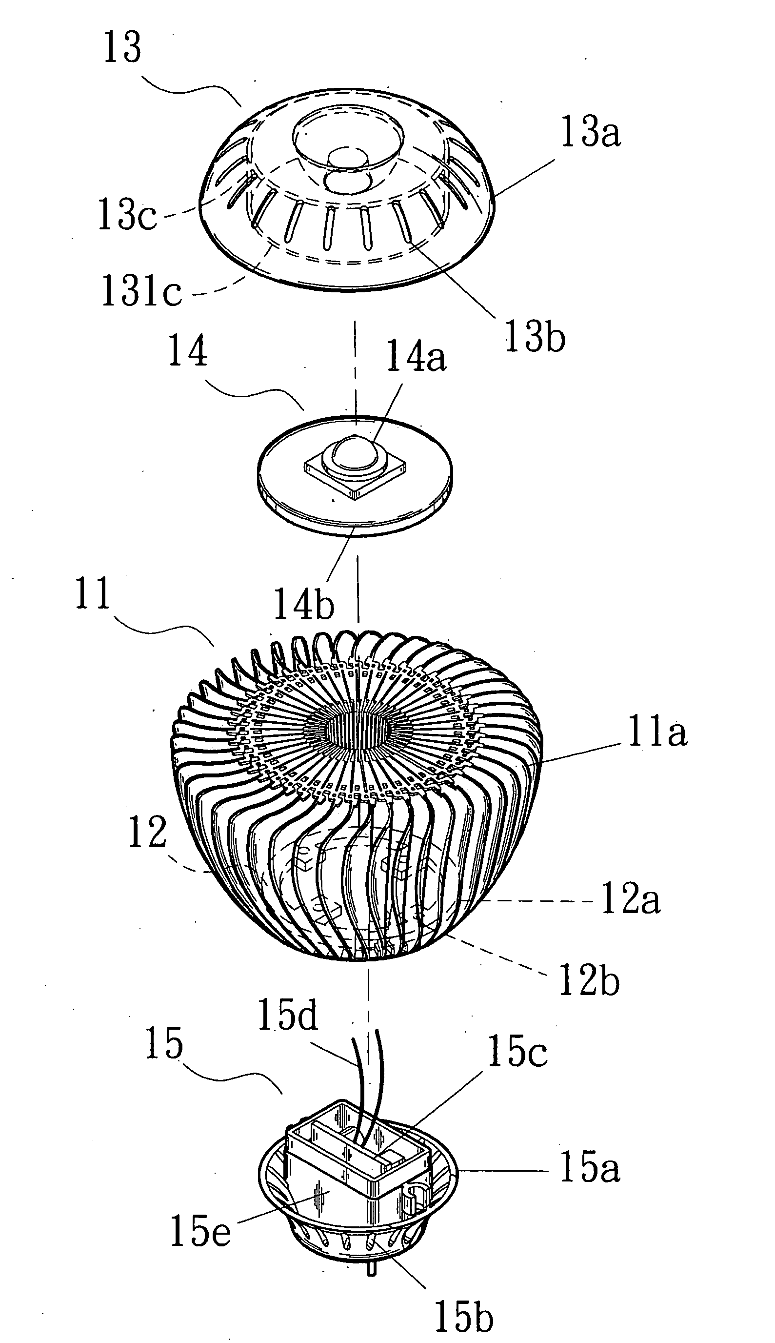
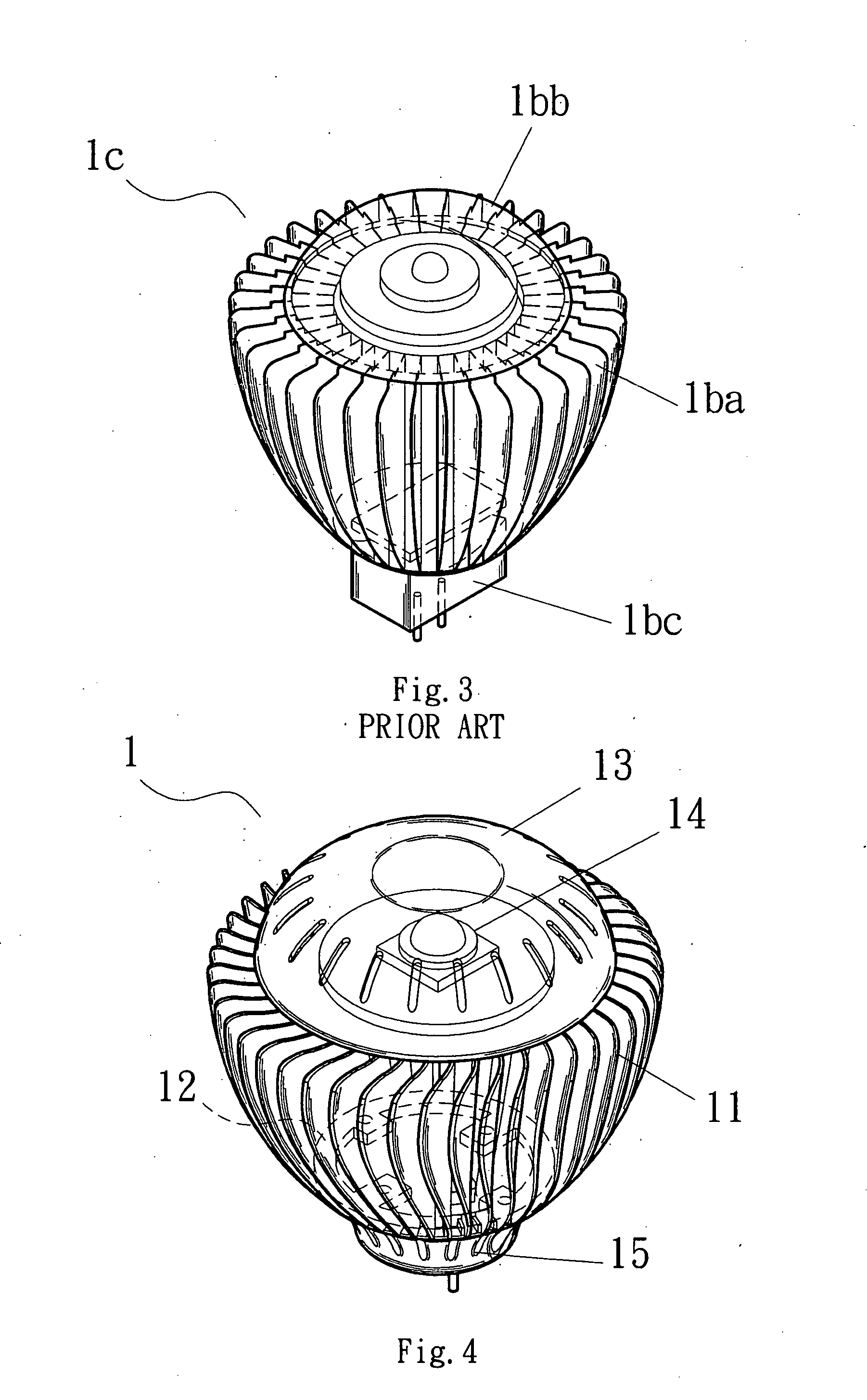
[0035]Please refer to FIGS. 4 to 11. The heat dissipation structure 1 of LED light of the present invention includes a lampshade 13 with ventilation holes 13b (as shown in FIGS. 4, 5 and 10), a power supply seat module 15 with ventilation holes 13b (as shown in FIGS. 5 and 11), a streamlined curved-surface thermal module 11 (as shown in FIG. 6) and an LED substrate module 14.

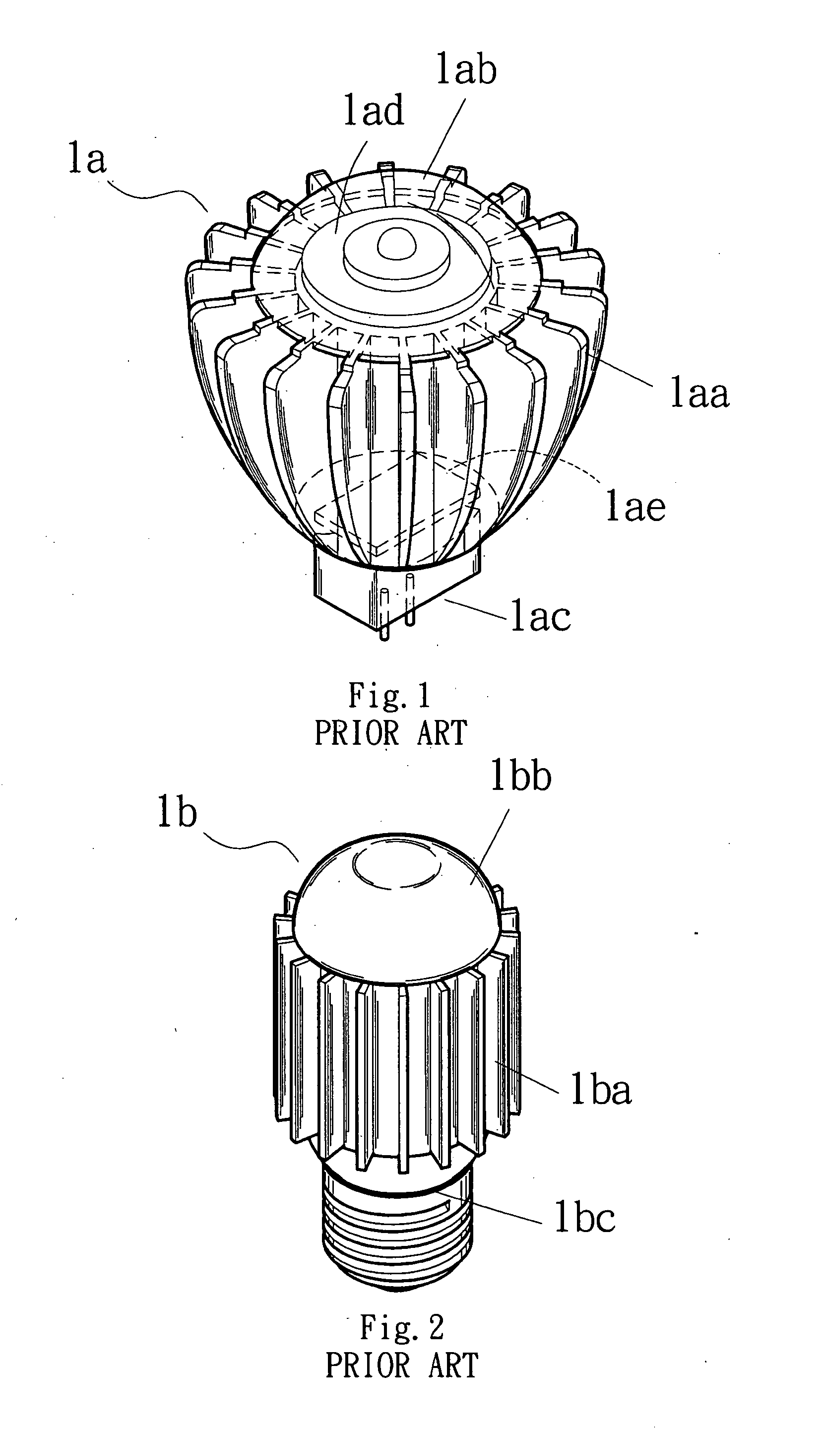
[0036]In the conventional LED light 1a, the LED substrate module 1ad is simply enclosed in a lampshade 1ab. The lampshade has no ventilation hole so that the LED substrate module 1ad is airtight sealed. In this case, the heat can be hardly dissipated outward. As a result, the high-temperature components on the LED substrate module 1ad often overheat to accelerate luminous decay of the LED light.

[0037]In contrast, the lampshade 13 with ventilation holes 13b (as shown in FIGS. 4, 5 and 10) of the present invention is composed of an inner casing 13c and an outer casing 13a. The LED substrate module 14 is placed int...


PUM


Abstract

A heat dissipation structure of LED light, including a ventilation lampshade, a ventilation power supply seat module and a streamlined curved-surface thermal module. The ventilation lampshade and the ventilation power supply seat module are formed with ventilation holes for expediting fluid convection and enhancing heat dissipation efficiency. The thermal module is composed of multiple radiating fins, which are adjacently annularly stacked to form the thermal module. The radiating fins are formed with streamlined curved surfaces, whereby fluid can more smoothly flow through the radiating fins to greatly enhance heat dissipation ability of the thermal module.

Description

BACKGROUND OF THE INVENTION[0001]The present invention is related to an improved heat dissipation structure of LED light, and more particularly to an LED light with higher heat dissipation ability.[0002]Currently, there is a trend of energy saving and carbon reduction all over the world. All kinds of high-brightness LED lights have been widely used in various fields to save power and energy. However, the LED chip modules of such high-brightness LED lights will generate high heat when working. The heat must be efficiently dissipated. Otherwise, the LED lights will malfunction. Therefore, it has become a critical issue how to dissipate the heat generated by the LED chip modules so as to keep the LED lighting systems functioning normally. In general, radiating fins are attached to the surfaces of the heat-generating components of the LED chip modules to conduct and dissipate the heat out of the LED lighting systems. Accordingly, the LED chip modules are protected from overheating so as...

Claims


Application Information

Patent Timeline
Patent Type & Authority Applications(United States)
IPC IPC(8): H01J61/52
CPCF21Y2101/02F21K9/13F21V3/02F21V29/83F21V29/74F21V29/773F21V29/506F21K9/23F21Y2115/10
Inventor WU, YA LI
Owner WU YA LI
Why Eureka
Try Eureka