Ocular Imaging System

a technology of ocular imaging and ocular scleral structure, which is applied in the field of optical devices and instruments for ophthalmological examination, can solve the problems of limiting in turn the eye regions and structural details apparent to the physician, patient discomfort, and patient's eyes being painfully sensitive to light for hours afterward

Active Publication Date: 2010-02-04
UNIV OF SOUTHERN CALIFORNIA +1
View PDF8 Cites 39 Cited by
  • Summary
  • Abstract
  • Description
  • Claims
  • Application Information

AI Technical Summary

Benefits of technology

[0011]The present disclosure addresses this need by providing an ocular imaging system that obviates the need for mydriasis or h...

Problems solved by technology

Examinations to obtain such images are often not performed because the pupil naturally restricts the field of view, thereby limiting in turn the eye regions and structural detail apparent to the physician.
Mydriasis, the drug-induced dilation of the pupil, allows sufficient light into the eye to permit detailed colored imaging of the retina, but necessitates extra time to induce dilation, and furthermore makes the patient's eyes painfully sensitive to lig...

Method used


Image

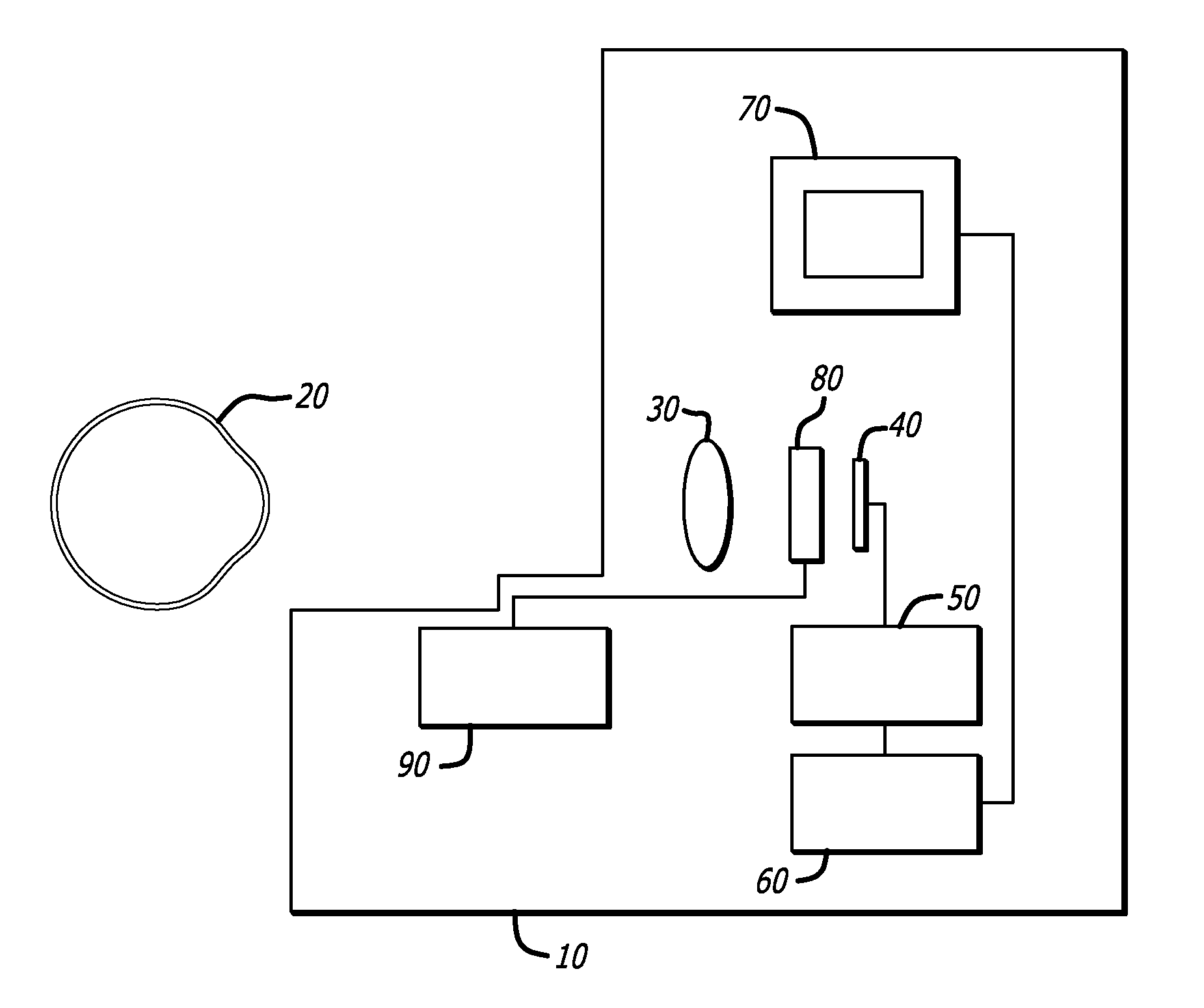
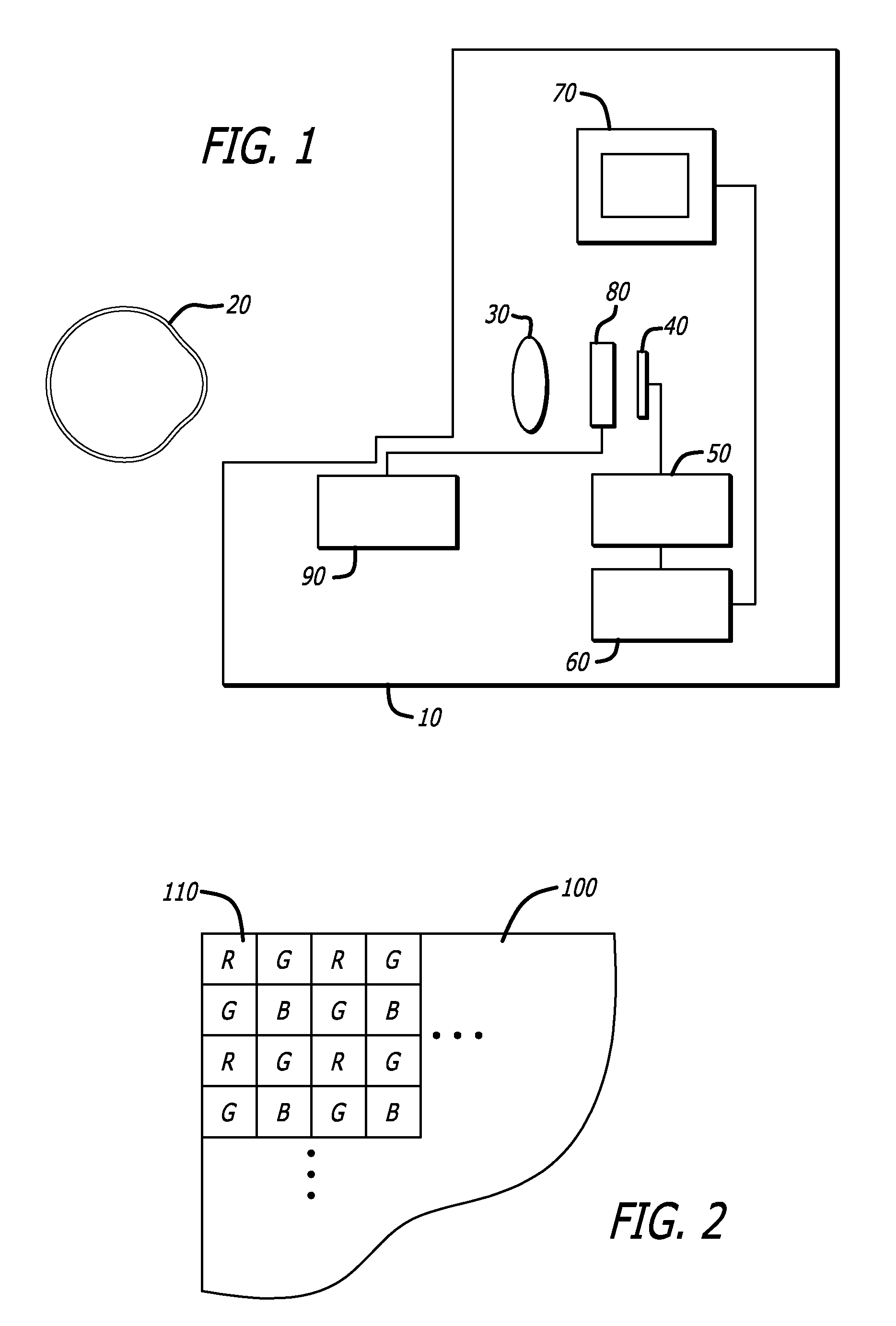
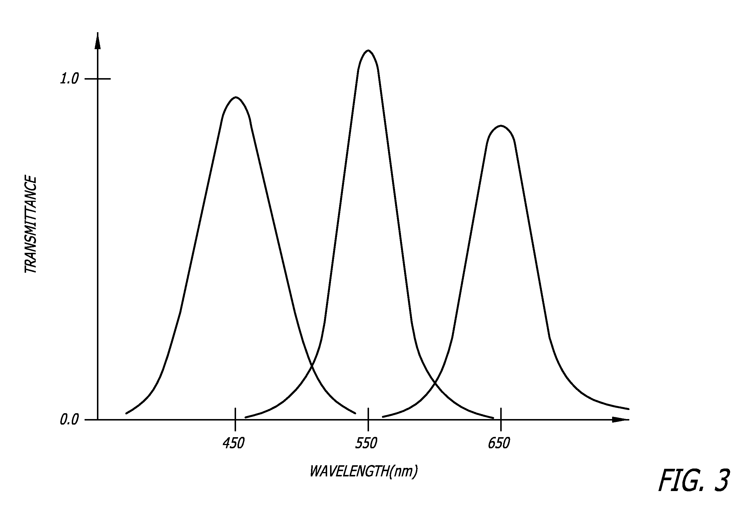
  • Ocular Imaging System
  • Ocular Imaging System
  • Ocular Imaging System

Examples


Embodiment Construction

[0016]“Ambient light” as used here refers at illuminance levels between about 10 and about 100 lux.

[0017]“High-sensitivity” when applied to an image sensor array refers to an array that yields a measurable response to light of illuminance less than about 0.01 lux.

[0018]“High-resolution” when used to describe the image sensor array refers to resolution of at least about 500 pixels in either the horizontal or vertical direction.

[0019]“Low light” refers to light of illuminance levels less than about 10 lux.

[0020]“Imaging” refers to generation of a visual depiction of an object, whether or not that depiction is tangible, and includes both evanescent visual inspection and depictions.

[0021]Unless otherwise specified, other technical terms take the meanings specified in the McGraw-Hill Dictionary of Scientific and Technical Terms, 6th edition.

[0022]Low-light monochrome viewing devices recently developed for military and law enforcement applications, as described for example in U.S. Pat. No...


PUM


Abstract

An imaging system for examining the interior structure of the eye at high-resolution under ambient light without the need for chemical dilation of the pupil.

Description

CROSS-REFERENCE TO RELATED APPLICATIONS[0001]This application claims priority from provisional application 61 / 048,180, “Low Light Level Imaging System for Ophthalmological Examination”, filed Apr. 26, 2008, which is hereby incorporated by reference in its entirety.STATEMENT REGARDING FEDERALLY SPONSORED RESEARCH[0002]This research was funded in part through the National Science Foundation Engineering Research Center (ERC) on Biomimetic MicroElectronic Systems, Grant Number NSF EEC-0310723. The government may therefore have certain rights.BACKGROUND[0003]1. Field[0004]The present disclosure relates generally to optical devices and instrumentation for ophthalmological examination.[0005]2. General Background[0006]Detailed images of internal structures of the retina allow detection of ocular pathology at an earlier, more treatable stage. Examinations to obtain such images are often not performed because the pupil naturally restricts the field of view, thereby limiting in turn the eye re...

Claims


Application Information

Patent Timeline
IPC IPC(8): A61B3/10
CPCA61B3/14A61B3/12
Inventor TANGUAY, JR., ARMAND R.HUMAYUN, MARK S.
Owner UNIV OF SOUTHERN CALIFORNIA
Why Eureka
Try Eureka