Fluorescent tube replacement having longitudinally oriented leds

a technology of leds and fluorescent tubes, applied in the manufacture of electric discharge tubes/lamps, lighting and heating apparatuses, lighting support devices, etc., can solve problems such as bright spots on light, and achieve uniform light output

Active Publication Date: 2010-02-04
ILUMISYS
View PDF102 Cites 93 Cited by
  • Summary
  • Abstract
  • Description
  • Claims
  • Application Information

AI Technical Summary

Benefits of technology

[0003]Known lights including LEDs provide directional light output that may result in the appearance of bright spots on the light. Thus, known lights including LEDs may appear different from fluorescent lights, which are characterized by their uniform light distribution. An LED-based light according to the present invention can provide a more uniform light output than the some known lights including LEDs in order to more closely match the light distribution of a fluorescent light. In general, an LED-based light for replacing a conventional fluorescent tube in a fixture includes an elongate light transmitting rod defining a bore. At least one LED is positioned at one or both ends of the rod and oriented to produce light longitudinally into a portion of the rod radially outward of the bore. At least one connector is physically coupled to an end of the rod and electrically coupled to the at least one LED, and the at least one connector is adapted for physical and electrical conne

Problems solved by technology

Known lights including LEDs provide directional light output t

Method used


Image

  • Fluorescent tube replacement having longitudinally oriented leds
  • Fluorescent tube replacement having longitudinally oriented leds
  • Fluorescent tube replacement having longitudinally oriented leds

Examples


Embodiment Construction

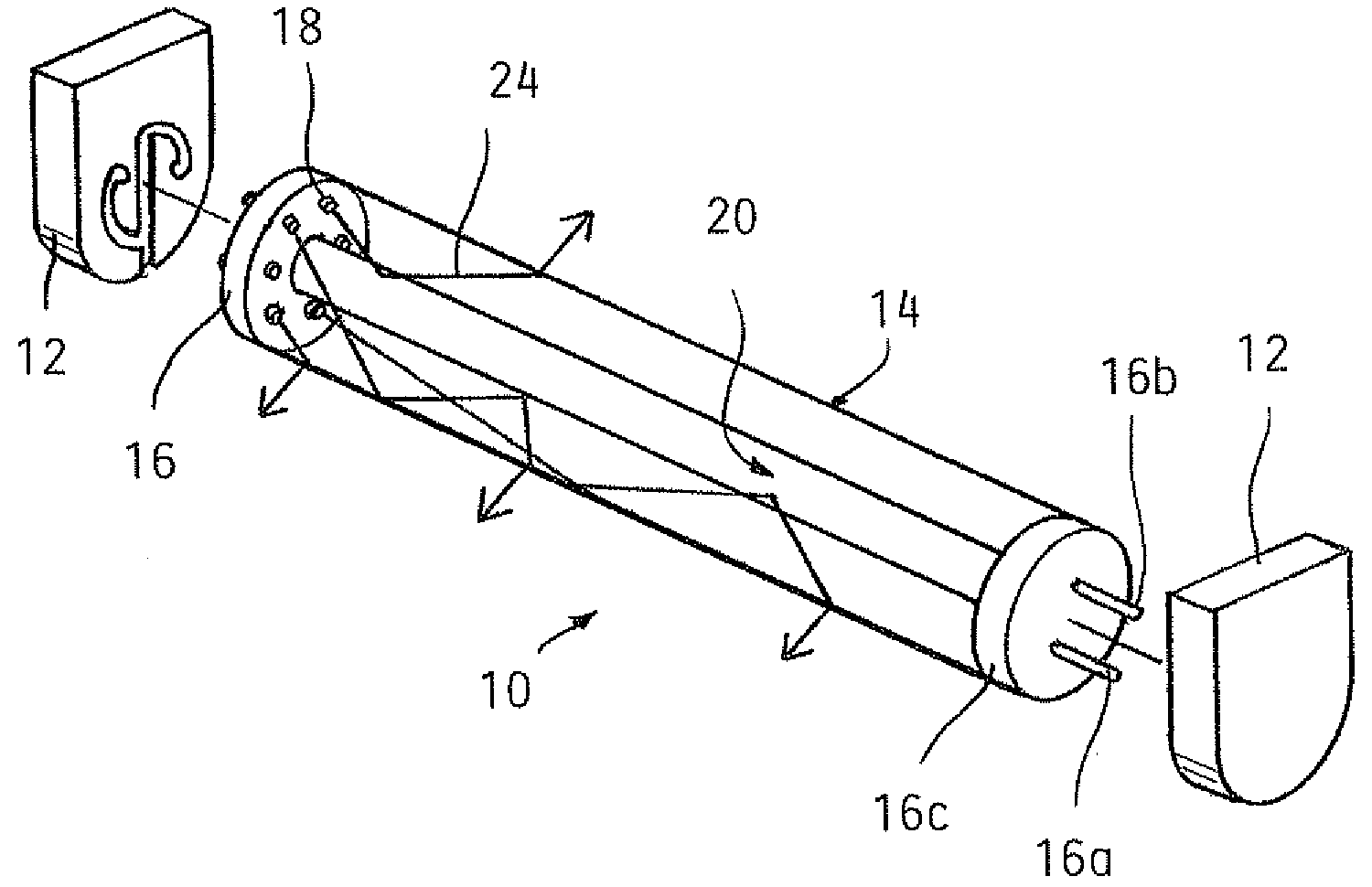
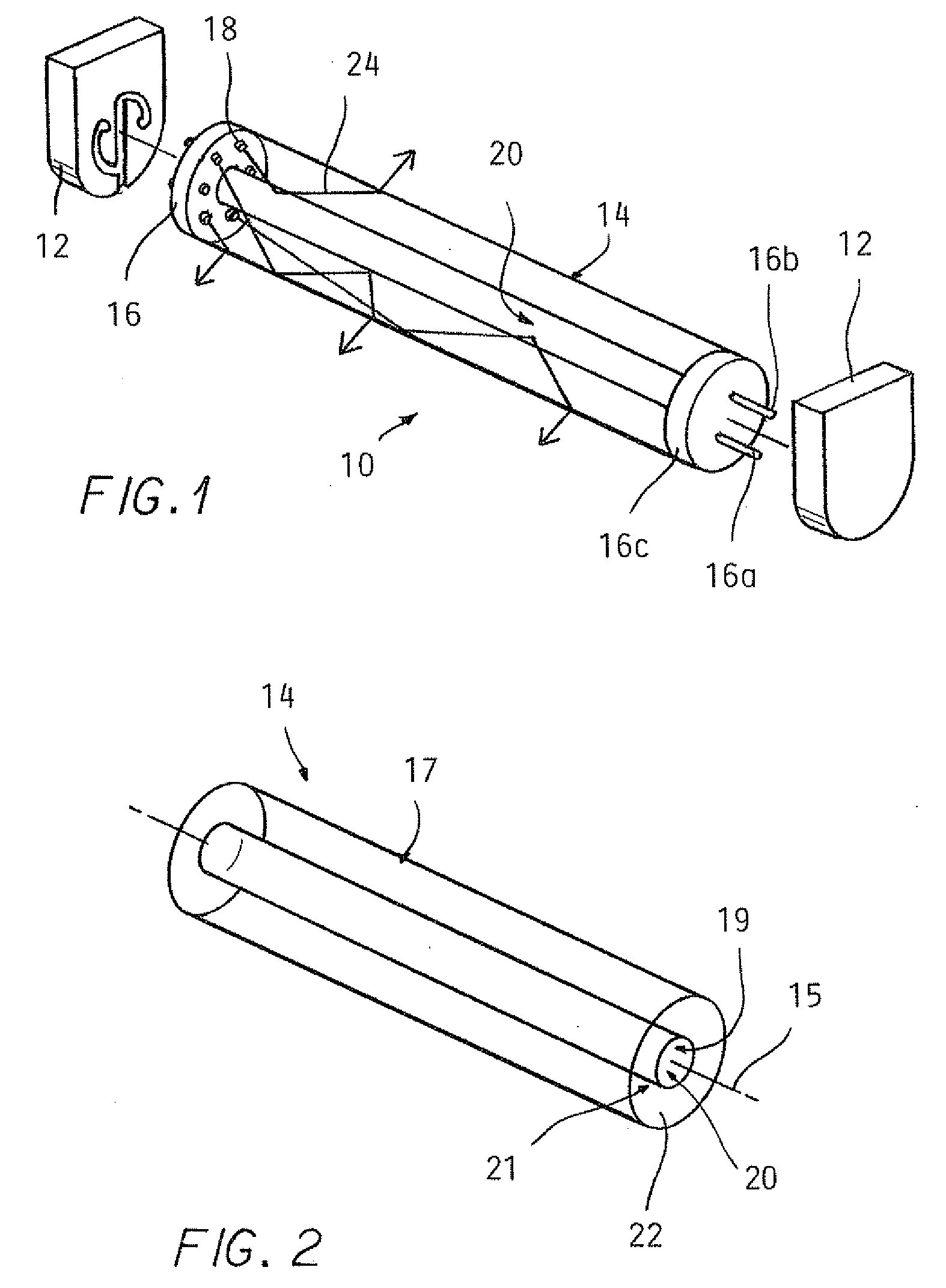
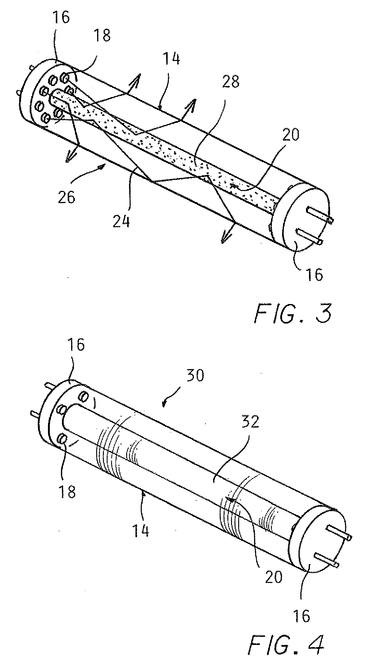
[0014]Embodiments of an LED-based light for replacing a conventional fluorescent tube in a fixture are illustrated in FIGS. 1-7. FIG. 1 illustrates an LED-based light 10 for use in a fixture 12 designed to accept conventional fluorescent tubes. The light 10 includes an elongate light transmitting rod 14, bi-pin end caps 16, and LEDs 18 positioned between the rod 14 and one of the end caps 16.

[0015]The rod 14 as shown in FIG. 2 defines a longitudinal axis 15, an outer surface 17, an inner surface 19, and two end surfaces 21 extending radially between the outer surface 17 and inner surface 19. A solid body portion 22 is the mass between the outer surface 17 and inner surface 19. While not illustrated to scale, the rod 14 can be approximately 48″ long with a 0.625″, 1.0″, or 1.5″ diameter for engagement with the fluorescent fixture 12. The rod 12 can be made from polycarbonate, acrylic, glass or another light transmitting material. That is, the rod 14 can be transparent or translucent....


PUM

PropertyMeasurementUnit
Lengthaaaaaaaaaa
Lightaaaaaaaaaa

Abstract

An LED-based light for replacing a conventional fluorescent tube in a fixture is provided. The LED-based light includes an elongate light transmitting rod defining a bore and at least one LED positioned at one or both ends of the rod and oriented to produce light longitudinally into a portion of the rod radially outward of the bore. At least one connector is physically coupled to an end of the rod and electrically coupled to the at least one LED. The at least one connector is adapted for physical and electrical connection to the fixture. In operation, the directional light produced by the at least one LED is dispersed by way of reflection, refraction, and/or diffusion while traveling longitudinally through the rod to reduce the appearance of bright spots.

Description

TECHNICAL FIELD[0001]The present invention relates to an LED-based light for replacing a conventional fluorescent tube in a fluorescent fixture.BACKGROUND[0002]Light emitting diodes (LEDs) have many advantages over fluorescent lights. LEDs are more efficient, last longer, and are less sensitive to vibrations and low temperatures. To take advantage of the benefits of LEDs, lights in the shape of conventional fluorescent tubes have been constructed to include LEDs. Known fluorescent tube-shaped lights using LEDs are constrained by the directional light output of the LEDs, in contrast to the uniform non-directional light output of fluorescent tubes.BRIEF SUMMARY[0003]Known lights including LEDs provide directional light output that may result in the appearance of bright spots on the light. Thus, known lights including LEDs may appear different from fluorescent lights, which are characterized by their uniform light distribution. An LED-based light according to the present invention can ...

Claims


Application Information

Patent Timeline
IPC IPC(8): F21V5/00F21V21/00H01J9/00
CPCF21Y2103/022F21Y2101/02F21V7/043F21V7/22F21Y2103/003F21K9/17F21K9/50F21K9/27F21K9/60F21Y2103/10F21Y2115/10F21Y2103/33F21V7/24F21V7/28F21K9/61F21V7/04F21S2/00F21Y2103/00
Inventor SIMON, DAVID L.IVEY, JOHN
Owner ILUMISYS
Why Eureka
Try Eureka