Buffering control method, and buffering control device

a buffering control and control method technology, applied in the field of buffering control methods, can solve the problems of complex control, lack of top sound of music pieces, and inability to directly communicate the generation of errors to the buffering control part in the system,

Active Publication Date: 2010-02-04
PANASONIC SEMICON SOLUTIONS CO LTD
View PDF14 Cites 0 Cited by
  • Summary
  • Abstract
  • Description
  • Claims
  • Application Information

AI Technical Summary

Benefits of technology

[0089]According to the present invention, since when performing digital dubbing of mainly the music data of CD, the buffering of the main data is carried out on the basis of the synchronization signal of the sub data, the time difference from detecting the buffering start point of a music piece to starting the buffering is gone, thereby enabling performing buffering fr...

Problems solved by technology

Particularly, with accompanied by the high speed dubbing in recent years, the time difference that is caused by going through the system control part provides larger influences as the transfer rate of data is high, and which results in fatal problems such as lacking of the top appearing sound of the music piece or noise generation at the end of the music piece when reproducing the recording medium such as an MD after the dubbing.
Further, when errors have arisen in the reproduced data by the influences by such as vibrations when reproducing an optical d...

Method used


Image

  • Buffering control method, and buffering control device
  • Buffering control method, and buffering control device
  • Buffering control method, and buffering control device

Examples


embodiment 1

[0162]Hereinafter, embodiments of the present invention will be described with reference to the drawings.

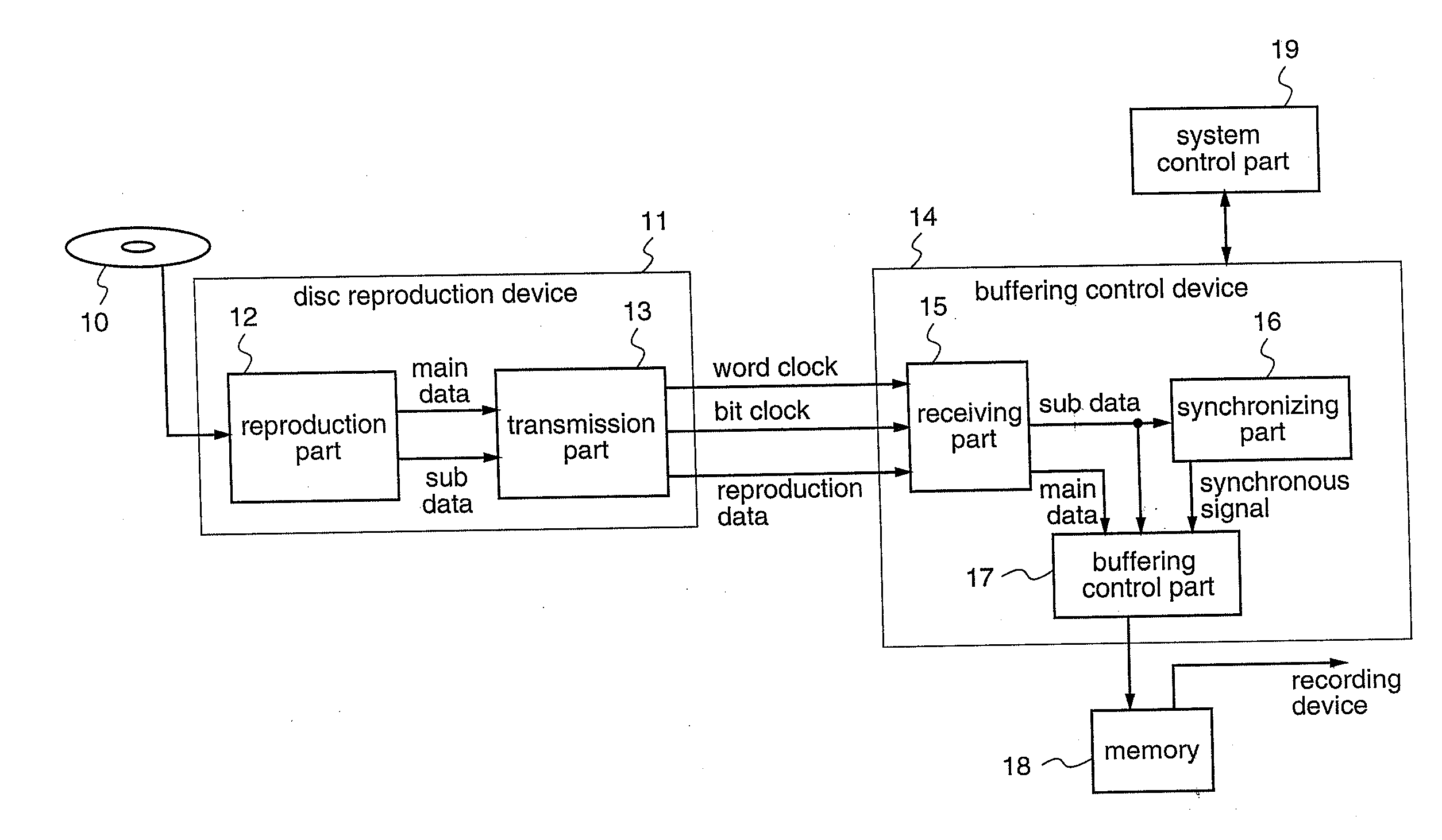
[0163]The buffering control device according to a first embodiment of the present invention is constituted so as to enable, when performing digital dubbing of such as music data from a CD player (disc reproduction device) for reproducing an optical disc to such as a portable audio system, to start buffering from a correct position in temporarily buffering the received main data into a memory device as a preprocessing up to writing down the data into the recording medium after performing compression processing of the data.

[0164]FIG. 1 is a diagram illustrating a construction of a dubbing system which performs digital dubbing utilizing a buffering control device according to the first embodiment of the present invention.

[0165]In FIG. 1, the disc reproduction device 11 is constructed similarly to the conventional disc reproduction device 11 shown in FIG. 26, and this device is inten...

embodiment 2

[0197]The buffering control device according to a second embodiment of the present invention is intended to perform interpolation of address in the address obtaining part in the buffering control part 17 thereby to interpolate the lacking address.

[0198]More particularly, while in the buffering control device of the above-described first embodiment the address obtaining part 91 in the buffering control part 17 is intended to obtain the address information which is included in the sub data, there may arise cases where the address information cannot be detected due to errors in the disc reproduction device 11 or errors in the transfer process from the disc reproduction device 11, similarly as that the synchronous signal cannot be detected due to errors in the disc reproduction device 11 or errors in the transfer process from the disc reproduction device 11. In such case, if the comparison address for detecting the coincidence with the designated address is forfeited, the coincidence si...

embodiment 3

[0213]The buffering control device according to a third embodiment of the present invention is intended to detect the abnormality of the reproduced data on the basis of the sub data in the buffering control device, thereby enabling to automatically halt the buffering without passing through any processing by the system control part.

[0214]More particularly, when there arises an error in the reproduced data in the disc reproduction device or in the data transfer path during buffering the main data, it is not possible to judge this occurrence of error based on the main data, and therefore, it was general that the buffering is halted when the content of the sub data is confirmed by the system control part 19 or when the abnormality of the reproduced data is judged on receipt of the error notification from the disc reproduction device. However, due to that the system control part carries out the abnormality judgment and the buffering halting processing at the abnormality detection, the l...


PUM


Abstract

When receiving the reproduced data from the optical disc and buffering same, the buffering from the correct position can be started on the basis of the synchronous signal and the address information included in the sub data which was received simultaneously.
There is provided a method for controlling the buffering of the main data which is reproduced from the optical disc, in which the main data and the sub data are received with taking word clocks which are partitioning timings having plural bits of the main data as a unit as references, a synchronous signal which is in synchronization with the main data is generated, and the buffering of the main data is started on the basis of the synchronous signal.

Description

TECHNICAL FIELD[0001]The present invention relates to a buffering control method, a buffering control device, a data transfer device, and a data transfer format for receiving data which is reproduced from an optical disc and buffering same, and more particularly, to those which can start buffering from a correct position when recording digital data signal which is reproduced from an optical disc device such as a CD layer into another recording medium.BACKGROUND ART[0002]Conventionally, as an optical disc on which such as music data are recorded, for example, a CD (Compact Disc) is widely used.[0003]The disc for music CDs has recorded therein music data such as of non-compressed and the usual CD disc has a diameter of 12 cm. To the contrary, in order to improve the portability, it is often practiced that the music data is compressed and the compressed music data is digitally dubbed into an MD (Mini Disc) to enable carrying on of same.[0004]Recently, by performing digital dubbing into...

Claims


Application Information

Patent Timeline
IPC IPC(8): G11B20/12G11B20/18
CPCG11B20/10527G11B20/10222G11B20/1876G11B27/10G11B27/3063G11B2020/10546G11B2020/10592G11B2020/10601G11B2020/1062G11B2020/10685G11B2020/10731G11B2020/10759G11B2020/10824G11B2020/10833G11B2020/10842G11B2020/10972G11B2020/10981G11B2020/1267G11B2020/1271G11B2020/1287G11B2020/1843G11B2220/2537G11B2220/2545G11B19/044G11B20/10037G11B20/1403
Inventor SHIMIZU, SHIROKASHII, NAOYUKIYAO, HIROSHIMATSUI, KIYOKATSU
Owner PANASONIC SEMICON SOLUTIONS CO LTD
Why Eureka
Try Eureka