
Local mobility anchor relocation and route optimization during handover of a mobile node to another network area

a technology of local mobility anchor and network area, which is applied in the direction of wireless network protocols, electrical equipment, wireless commuication services, etc., can solve the problems of high packet delay, inefficient routing, and inefficient routing

Active Publication Date: 2010-02-04
PANASONIC INTELLECTUAL PROPERTY CORP OF AMERICA
View PDF4 Cites 55 Cited by
  • Summary
  • Abstract
  • Description
  • Claims
  • Application Information

AI Technical Summary

Benefits of technology

[0027]According to an advantageous embodiment of the invention, the information on whether to use route optimization is a flag, which is easy to set or unset.
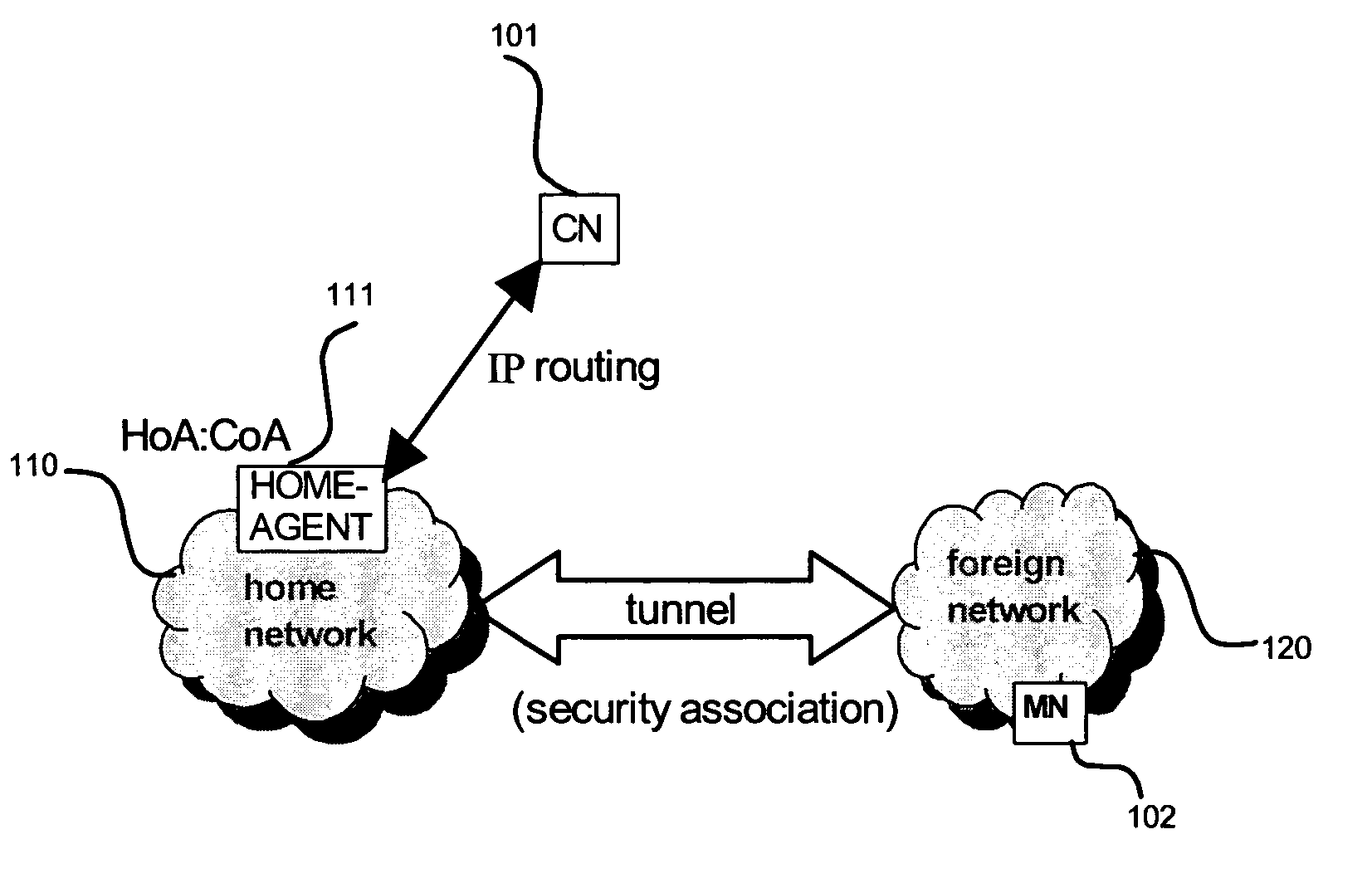
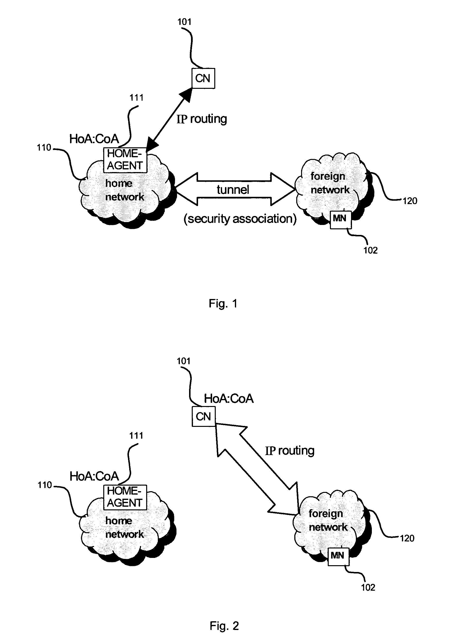
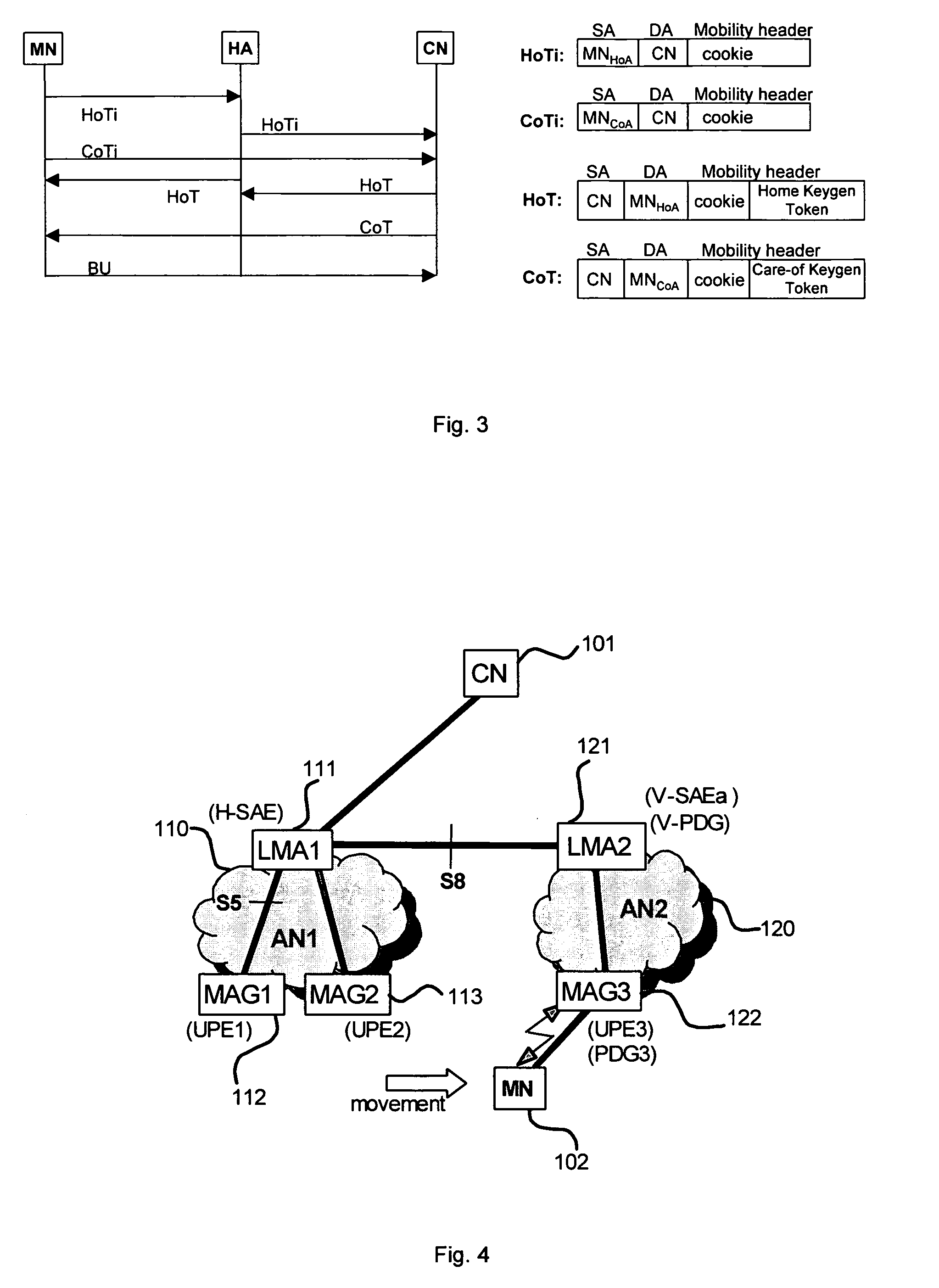
[0037]In addition, the correspondent node is instructed to exchange the data packets with the mobile node on the first data packet route via the first local mobility anchor. Thereafter, information on whether to use route optimization for the first data packet route between the correspondent node and the mobile node, and information on addresses of the correspondent node and the mobile node used for exchanging the data packets s requested from the policy control entity in the first network area. Then, in case route optimization is to be used for the first data packet route between the correspondent node and the mobile node, the correspondent node is instructed to exchange the data packets with the mobile node on a third data route via the third local mobility anchor. The route optimization for the third network area allows for a more direct route between the correspondent node and the mobile node, thus reducing data delays.

Problems solved by technology

A drawback is that if the mobile node is far away from the home network and the correspondent node is close to the mobile node, the communication path is unnecessarily long, resulting in inefficient routing and high packet delays.
This results in inefficient routing and in high data packet delays, which is e.g. critical for real-time services.

Method used


Image

  • Local mobility anchor relocation and route optimization during handover of a mobile node to another network area
  • Local mobility anchor relocation and route optimization during handover of a mobile node to another network area
  • Local mobility anchor relocation and route optimization during handover of a mobile node to another network area

Examples


Embodiment Construction

[0061]The following paragraphs will describe various embodiments of the invention. For exemplary purposes only, most of the embodiments are outlined in relation to a NetLMM communication system according to the NetLMM discussed in the Background Art section above. It should be noted that the invention may be advantageously used for example in connection with a mobile communication system such as the NetLMM communication system previously described, but the invention is not limited to its use in this particular exemplary communication network.

[0062]The explanations given in the Technical Background section above are intended to better understand the mostly NetLMM specific exemplary embodiments described herein and should not be understood as limiting the invention to the described specific implementations of processes and functions in the mobile communication network. Nevertheless, the improvements proposed herein may be readily applied in the architectures / systems described in the T...


PUM


Abstract

The invention relates to a method for managing the mobility of a mobile node that moves to a different network, but keeps the same IP address. It is proposed to perform route optimization by a Proxy MIP agent on behalf of the MN, thereby shortening the data-path while allowing network-based mobility. At session setup with a correspondent node, the PCC system in the home network derides whether route optimization is to be performed for the communication session. The PMIPa requests relevant information for the route optimization, including the decision for route optimization and the addresses of MN and CN, from the PCC system in the home network, when the MN attaches to the new network area. Accordingly, route optimization is performed by using the Return Routability Procedure according to MIPv6, thereby applying the MN's IP address as Home Address, and the PMIPa's address as Care-of Address of the MN.

Description

FIELD OF THE INVENTION[0001]The invention relates to a handover procedure in which a proxy mobile IP agent in a foreign network performs route optimization for a mobile node, while the mobility and route optimization remains transparent to the mobile node. Furthermore, the invention also relates to a local mobility anchor and a policy control and charging system that participate in the handover procedure, for setting up an optimized route.TECHNICAL BACKGROUND[0002]Communications systems evolve more and more towards an Internet Protocol (IP)-based network. They typically consist of many interconnected networks, in which speech and data is transmitted from one terminal to another terminal in pieces, so-called packets. IP packets are routed to the destination by routers in a connection-less manner. Therefore, packets comprise IP header and payload information, whereby the header comprises among other things source and destination IP address.[0003]For scalability reasons, an IP network ...

Claims


Application Information

Patent Timeline
IPC IPC(8): H04W36/00
CPCH04W8/082H04W80/04H04W8/087
Inventor VELEV, GENADIHAKENBERG, ROLFBACHMANN, JENS
Owner PANASONIC INTELLECTUAL PROPERTY CORP OF AMERICA
Learn More