Transmission terminal, reception terminal, and information distribution system

a technology of information distribution system and reception terminal, which is applied in the direction of wireless communication, wireless commuication services, instruments, etc., can solve the problem of retransmission uni

Active Publication Date: 2010-02-04
OKI ELECTRIC IND CO LTD
View PDF4 Cites 6 Cited by
  • Summary
  • Abstract
  • Description
  • Claims
  • Application Information

AI Technical Summary

Benefits of technology

[0018]The present invention provides a system where the potential for a legitimate reception terminal to successfully receive information and for an intercepting terminal to fail to receive information and to provide a system and a terminal with which wireless key delivery can be realized more securely.
[0020]According to the transmission terminal pertaining to the present invention, the transmission terminal transmits the redundant information to share the transmission information with the destination reception terminal, so in comparison to a case where the transmission terminal transmits only the transmission information, there become more bit errors in an intercepting terminal usually present in a position far from the destination reception terminal, and the transmission terminal can exhibit effects that are the same as a technique where the transmission terminal lowers its transmission output to transmit information.

Problems solved by technology

The delivery management unit causes the information generation unit to generate, and causes the transmission unit to retransmit, the redundant information when the transmission terminal determines that the destination reception terminal has not be able to receive the successful redundant information from the transmission terminal.

Method used


Image

  • Transmission terminal, reception terminal, and information distribution system
  • Transmission terminal, reception terminal, and information distribution system
  • Transmission terminal, reception terminal, and information distribution system

Examples


embodiment 1

[0052]The present embodiment is configured to estimate the bit error rate of a reception terminal on the basis of the radio wave propagation characteristic of an environment that has been measured beforehand and increase and deliver an information amount of transmission information to the extent that bit errors occur based on an arbitrary bit error rate (e.g., the bit error rate of the reception terminal) as a reference.

[0053]Thus, the embodiment makes it easier to generate bit errors in an intercepting terminal whose error rate is higher than the above-described bit error rate and, as a result, ensures that only an intended reception terminal can restore the correct transmission information.

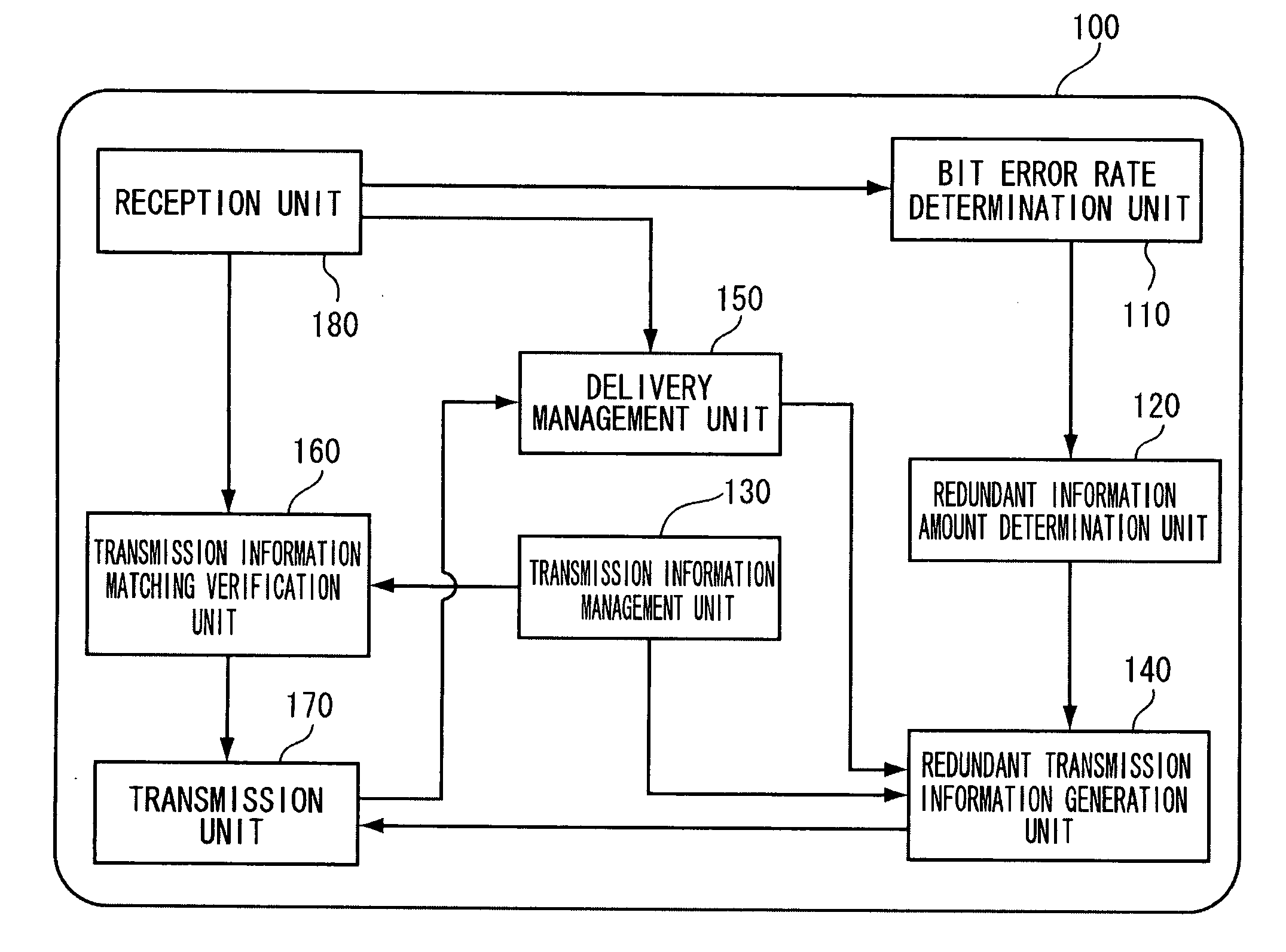
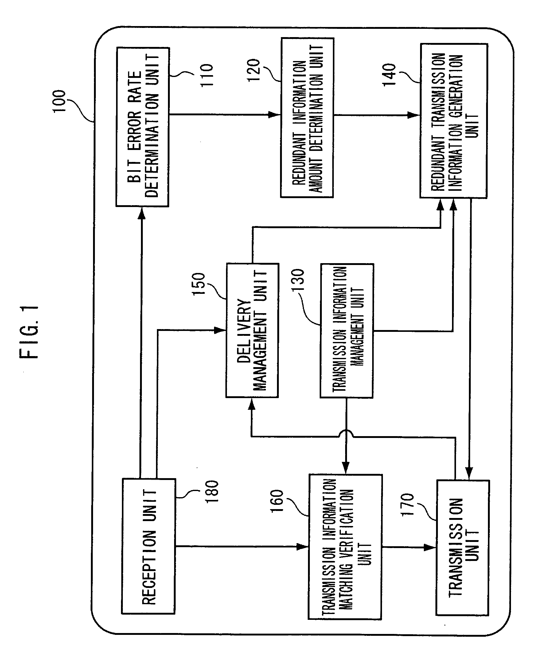
[0054]FIG. 1 is a functional block diagram of a transmission terminal 100 pertaining to embodiment 1. The transmission terminal 100 is equipped with a bit error rate determination unit 110, a redundant information amount determination unit 120, a transmission information management unit 130, a r...

embodiment 2

[0200]In the present embodiment, instead of estimating the bit error rate of the reception terminal 200 using the radio wave propagation characteristic as in embodiment 1, the transmission terminal 100 actually delivers the redundant transmission information a prescribed number of times and estimates the bit error rate of the reception terminal 200 from the error count at that time.

[0201]The information distribution system pertaining to embodiment 2 is, as in embodiment 1, configured by the transmission terminal 100 and the reception terminal 200. The reception terminal 200 is generally the same as the reception terminal 200 in embodiment 1, so only the transmission terminal 100 will be described.

[0202]FIG. 12 is a functional block diagram of the transmission terminal 100 pertaining to embodiment 2.

[0203]Here, only the redundant information amount determination unit 120, the redundant transmission information generation unit 140, the delivery management unit 150 and the bit error ra...

embodiment 3

[0243]In the present embodiment, there will be described a configuration and an operation that make it difficult for the intercepting terminal to identify the transmission information by including dummy information in the redundant transmission information.

[0244]In embodiment 3, the reception terminal 200 generates, and transmits to the transmission terminal 100, dummy redundant transmission information. Further, the reception terminal 200 transmits a successful reception reply and a resend request of that dummy information to the transmission terminal 100 as a dummy successful reception reply and a dummy resend request.

[0245]Thus, the intercepting terminal receives the dummy redundant transmission information and the dummy successful reception reply and resend request, and it becomes difficult for the intercepting terminal to discriminate which is true redundant transmission information, so it becomes difficult for the intercepting terminal to identify the transmission information....


PUM


Abstract

A transmission terminal includes an information generation unit, a transmission unit, a delivery management unit, and a reception unit. The information generation unit generates information that is to be transmitted to a destination reception terminal. The transmission unit transmits information that the information generation unit has generated. The delivery management unit manages transmission of information. The reception unit receives information that the destination reception terminal transmits. Furthermore, the information generation unit generates or receives transmission information that is to be transmitted to the destination reception terminal and generates redundant information for the destination reception terminal to restore the transmission information. The delivery management unit causes the information generation unit to generate, and causes the transmission unit to retransmit, the redundant information when the reception unit has not received a successful reception reply from the destination reception terminal.

Description

CROSS-REFERENCE TO RELATED APPLICATION [0001]This application claims priority under 35 USC 119 from Japanese Patent Application No. 2008-189583 filed on Jul. 23, 2008, the disclosure of which is incorporated by reference herein.BACKGROUND OF THE INVENTION[0002]1. Field of the Invention[0003]The present invention relates to a transmission terminal that transmits information, a reception terminal that receives that information, and an information distribution system that includes these terminals.[0004]2. Description of the Related Art[0005]In recent years, home wireless networks have become widespread. As wireless network systems that are currently becoming widespread, there are wireless LANs, whose purpose is to connect computer devices such as personal computers to the Internet. Henceforth, as wireless network systems that will newly become widespread in homes, digital information home appliance network systems and sensor network systems are expected.[0006]These networks will cooper...

Claims


Application Information

Patent Timeline
Patent Type & Authority Applications(United States)
IPC IPC(8): H04W84/02G06F21/00G06F21/60G06F21/62
CPCH04L1/1816H04L1/203H04W84/12H04W12/04
Inventor YAO, TAKETSUGUNAKAI, TOSHIHISAFUKUI, KIYOSHI
Owner OKI ELECTRIC IND CO LTD
Why Eureka
Try Eureka