
Method for operating an internal combustion engine, taking into consideration the individual properties of the injection devices

a technology of injection device and internal combustion engine, which is applied in the direction of electrical control, process and machine control, instruments, etc., can solve the problems of inaccurate ascertaining of actual operation methods, and achieve the effect of increasing reliability

Inactive Publication Date: 2009-10-13
ROBERT BOSCH GMBH
View PDF21 Cites 4 Cited by
  • Summary
  • Abstract
  • Description
  • Claims
  • Application Information

AI Technical Summary

Benefits of technology

The present invention provides a method and system for accurately monitoring the torque of an internal combustion engine. This is achieved by using compensating values that account for the individual properties of the injection device, such as the diameter of the nozzle opening or temperature dependence. These compensating values can be determined during manufacturing or later during maintenance. The use of these compensating values allows for improved monitoring of the engine, as errors can be recognized more quickly. The compensating values can be stored in a memory of the control unit and used for the entire service life of the engine. The method and system also involve transferring compensating values from functions outside the monitoring process, which saves resources and increases reliability. The transferred compensating values are subjected to a plausibility check to ensure their accuracy. The invention provides a computer program for the control unit of the internal combustion engine that implements the method. Overall, the invention provides a more accurate and reliable way to monitor the torque of an internal combustion engine.

Problems solved by technology

However, the typical operating methods are sometimes very inaccurate with regard to ascertaining the actual torque which, inter alia, is to be attributed to a large scatter of the individual properties of the injection devices.

Method used


Image

  • Method for operating an internal combustion engine, taking into consideration the individual properties of the injection devices
  • Method for operating an internal combustion engine, taking into consideration the individual properties of the injection devices
  • Method for operating an internal combustion engine, taking into consideration the individual properties of the injection devices

Examples


Embodiment Construction

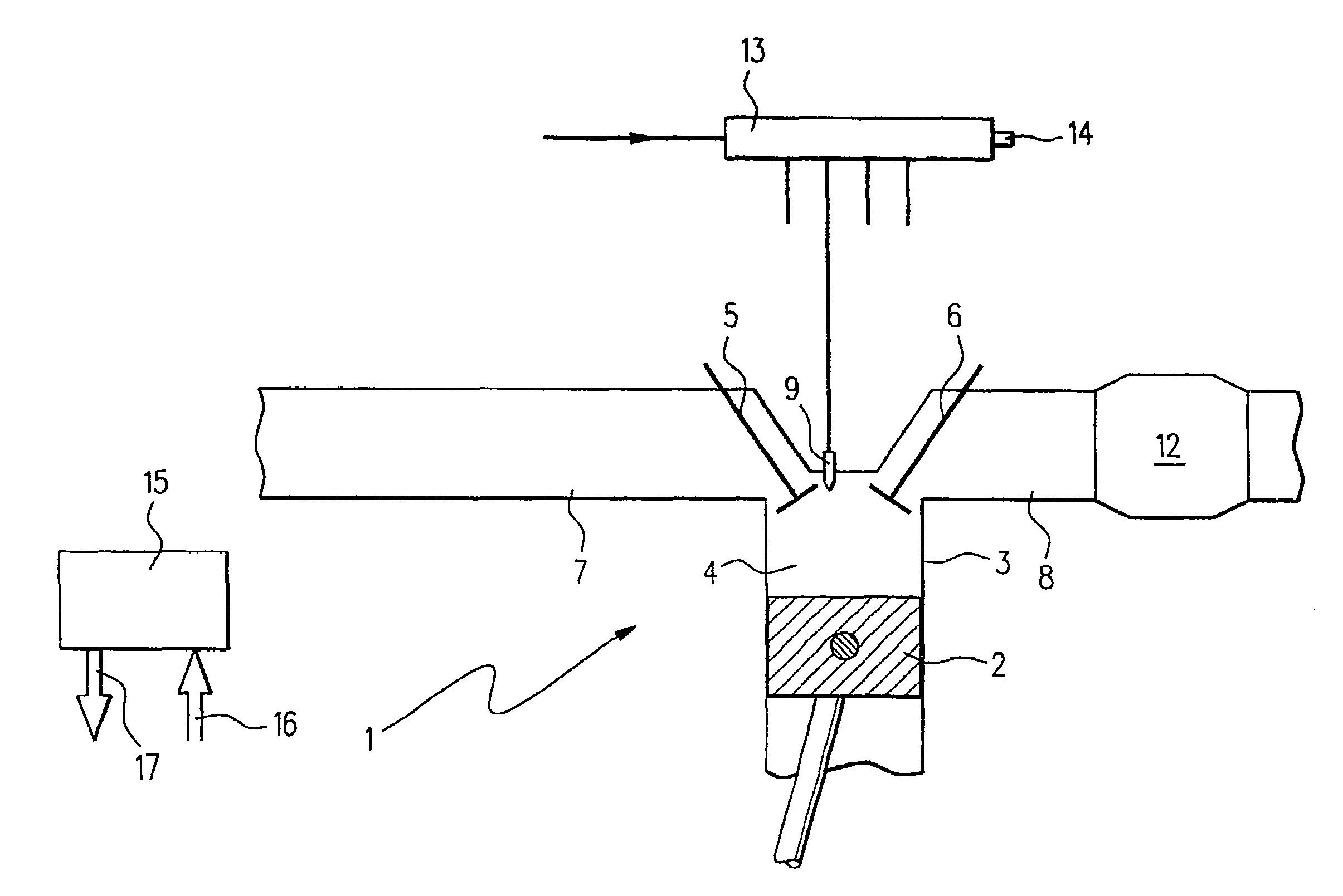
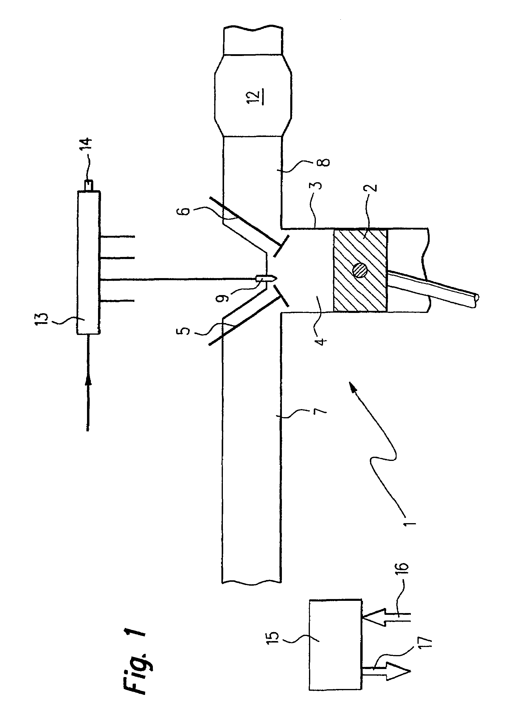
[0023]An internal combustion engine 1 of a motor vehicle, in which a piston 2 is movable back and forth in a cylinder 3, is illustrated in FIG. 1. Cylinder 3 is provided with a combustion chamber 4 which is delimited, inter alia, by piston 2, an inlet valve 5, and an outlet valve 6. An intake pipe 7 is coupled to inlet valve 5 and an exhaust pipe 8 is coupled to outlet valve 6.

[0024]A fuel injector 9 projects into combustion chamber 4 in the area of inlet valve 5 and outlet valve 6, via which fuel may be injected into combustion chamber 4. A catalytic converter 12, which is used for purifying the exhaust gases resulting due to the combustion of the fuel, is housed in exhaust pipe 8.

[0025]Fuel injector 9 is connected to a fuel accumulator 13 via a pressure line. In a similar way, the fuel injectors of the other cylinders of internal combustion engine 1 are also connected to fuel accumulator 13. Fuel accumulator 13 is supplied with fuel via a supply line. A mechanical fuel pump may be...


PUM

PropertyMeasurementUnit
torqueaaaaaaaaaa
pressureaaaaaaaaaa
volumeaaaaaaaaaa

Abstract

A method for operating an internal combustion engine, in which fuel is injected using an injection device into a combustion chamber of a cylinder of the internal combustion engine, a fuel quantity to be injected being ascertained as a function of individual properties of the injection device, and in which functional monitoring is performed, in which an actual torque is ascertained on the basis of performance quantities of the internal combustion engine and monitored for a deviation from a permissible torque. The individual properties of the injection device are taken into consideration when ascertaining the actual torque, where the functional monitoring is improved.

Description

FIELD OF THE INVENTION[0001]The present invention relates to a method for operating an internal combustion engine, in which fuel is injected using an injection device into a combustion chamber of a cylinder of the internal combustion engine, a fuel quantity to be injected being ascertained as a function of individual properties of the injection device, and in which functional monitoring is performed, during which an actual torque is ascertained on the basis of performance quantities of the internal combustion engine and monitored for deviation from a permissible torque. Furthermore, the present invention relates to a control unit for an internal combustion engine as well as a computer program for a control unit of this type.BACKGROUND INFORMATION[0002]Within the scope of typical operating methods, the actual torque actually delivered by the internal combustion engine is ascertained from various performance quantities of the internal combustion engine, such as an injection duration a...

Claims


Application Information

Patent Timeline
Patent Type & Authority Patents(United States)
IPC IPC(8): G01L3/00F02D41/14F02D41/24
CPCF02D41/2425F02D41/1497F02D41/008F02D2200/1004
Inventor GANGI, MARCOVON SCHWERTFUEHRER, GERIT
Owner ROBERT BOSCH GMBH
Learn More