

Method For Operating An Internal Combustion Engine, Taking Into Consideration The Individual Properties Of The Injection Devices
- Summary
- Abstract
- Description
- Claims
- Application Information
AI Technical Summary
Benefits of technology
Problems solved by technology
Method used
Image

Examples
Embodiment Construction
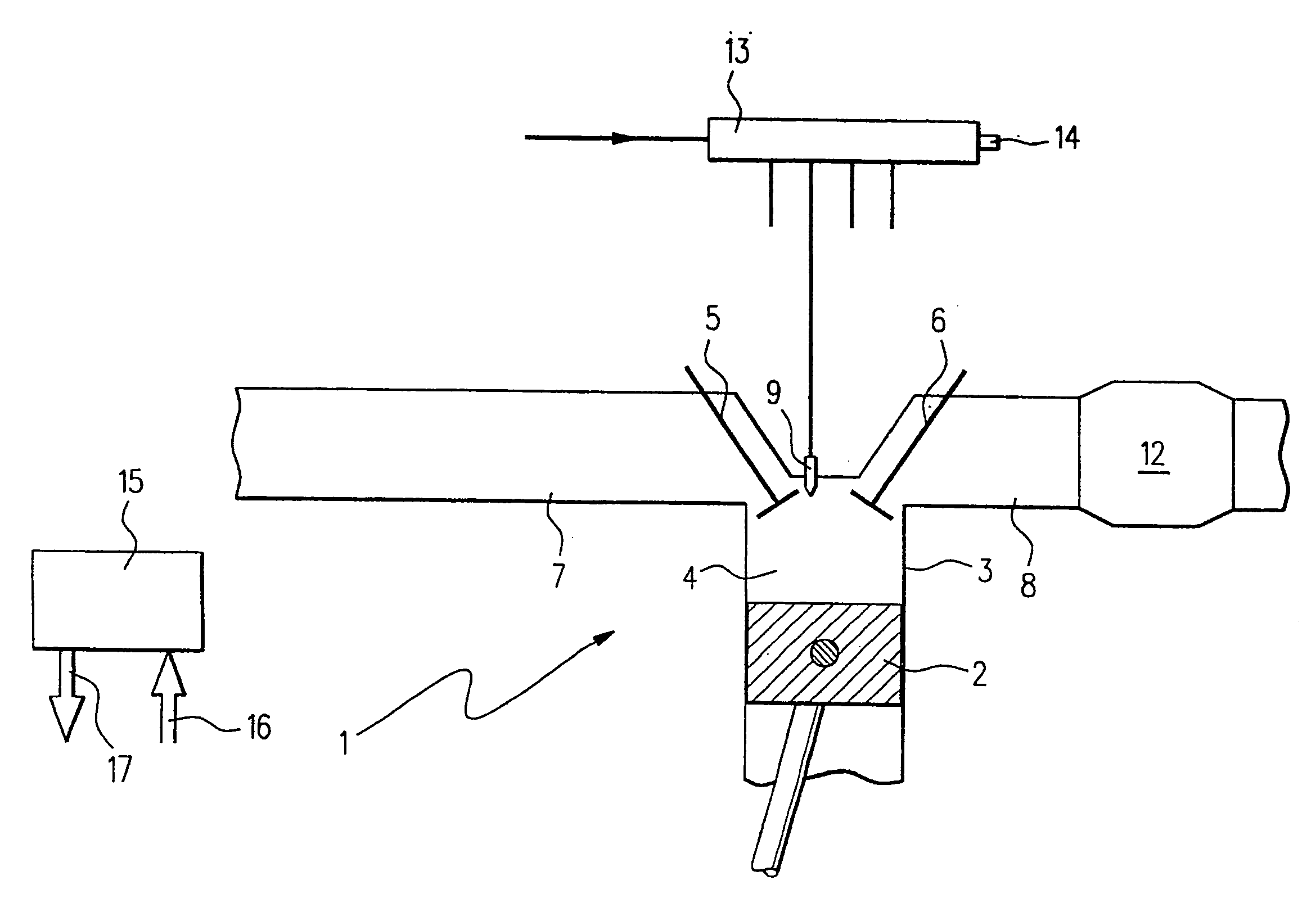
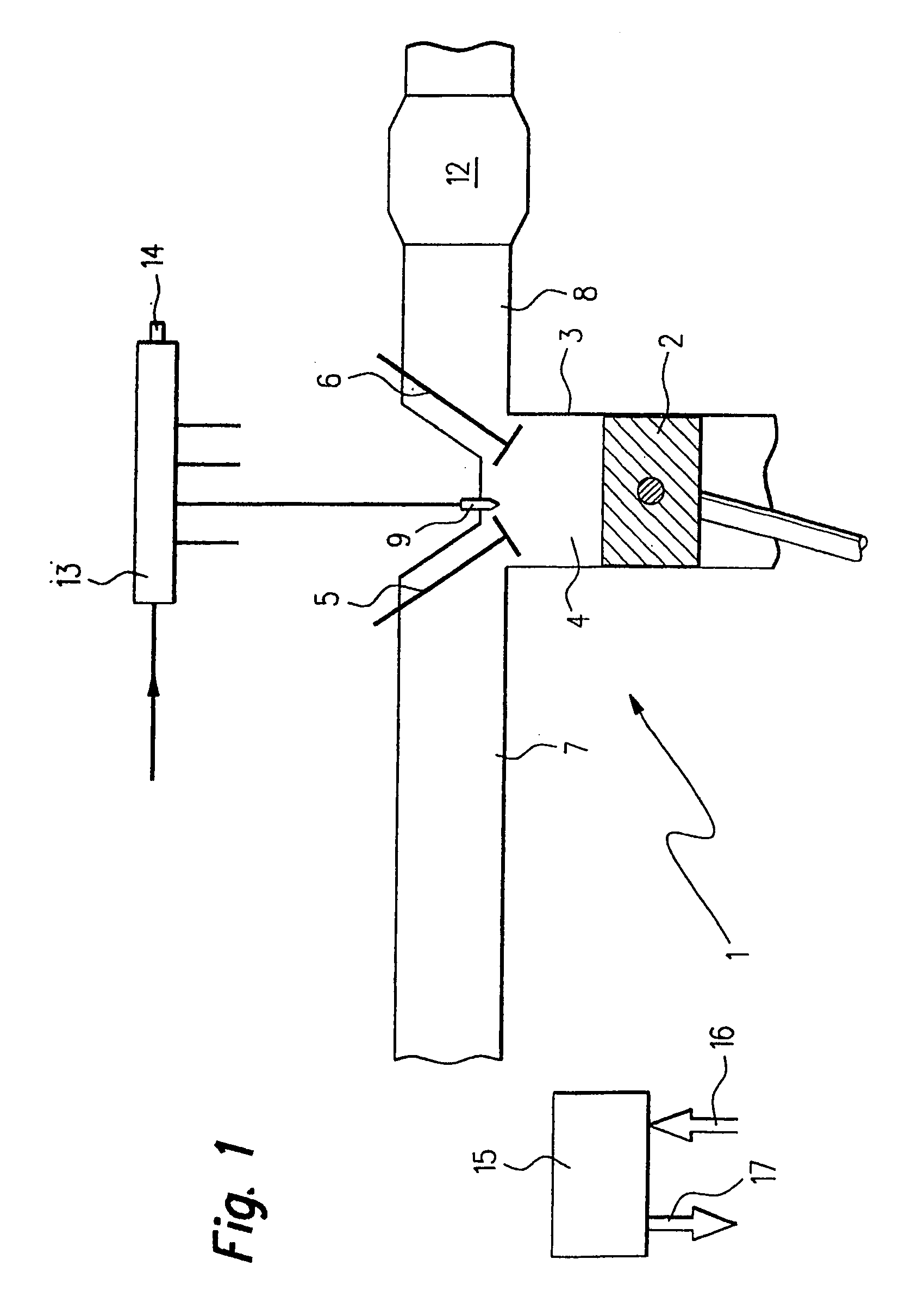
[0023]An internal combustion engine 1 of a motor vehicle, in which a piston 2 is movable back and forth in a cylinder 3, is illustrated in FIG. 1. Cylinder 3 is provided with a combustion chamber 4 which is delimited, inter alia, by piston 2, an inlet valve 5, and an outlet valve 6. An intake pipe 7 is coupled to inlet valve 5 and an exhaust pipe 8 is coupled to outlet valve 6.
[0024]A fuel injector 9 projects into combustion chamber 4 in the area of inlet valve 5 and outlet valve 6, via which fuel may be injected into combustion chamber 4. A catalytic converter 12, which is used for purifying the exhaust gases resulting due to the combustion of the fuel, is housed in exhaust pipe 8.
[0025]Fuel injector 9 is connected to a fuel accumulator 13 via a pressure line. In a similar way, the fuel injectors of the other cylinders of internal combustion engine 1 are also connected to fuel accumulator 13. Fuel accumulator 13 is supplied with fuel via a supply line. A mechanical fuel pump may be...
PUM
 Abstract
Description
Claims
Application Information