Wireless base station, wireless communication terminal, and wireless communication system

a wireless communication terminal and wireless communication technology, applied in the field of wireless communication terminals, wireless communication systems, wireless communication terminals, etc., can solve the problems of insufficient time taken by the communication terminal to receive contents, insufficient transmission of communication terminals, and broadcasting unnecessary pieces of information. , to achieve the effect of efficient transmission of information and large amount of information

Active Publication Date: 2010-02-04
PANASONIC INTELLECTUAL PROPERTY MANAGEMENT CO LTD
View PDF13 Cites 24 Cited by
  • Summary
  • Abstract
  • Description
  • Claims
  • Application Information

AI Technical Summary

Benefits of technology

[0013]Therefore, an object of the present invention is to solve the above-described conventional problems, and to provide: a wireless base station, which is capable of efficiently transmitting information to a wireless communication terminal moving and passing through a spot communication area at a high speed, the information...

Problems solved by technology

However, even if the technology disclosed in Patent Document 1 is used, when it is assumed that a communication terminal moves in a spot communication area or the like at a high speed, time taken by the communication terminal to receive contents has not been sufficiently reduced.
Since memory capacity...

Method used


Image

  • Wireless base station, wireless communication terminal, and wireless communication system
  • Wireless base station, wireless communication terminal, and wireless communication system
  • Wireless base station, wireless communication terminal, and wireless communication system

Examples


embodiment 1

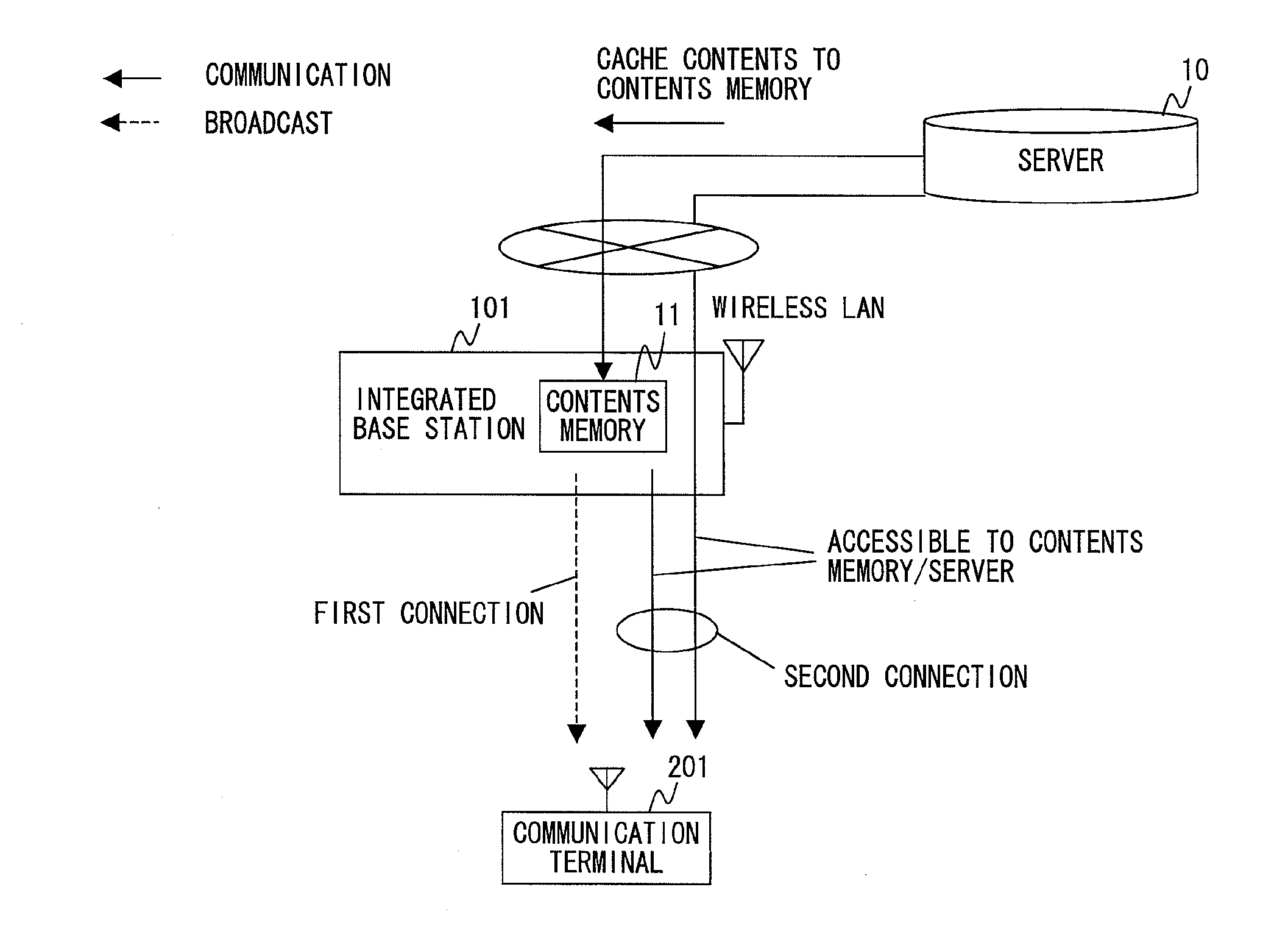
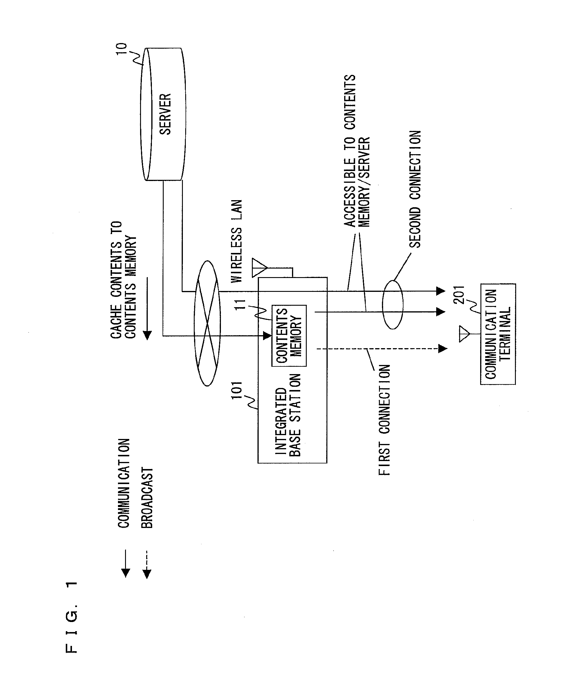
[0079]FIG. 1 is a schematic view illustrating an overall configuration of a wireless communication system according to embodiment 1 of the present invention. In FIG. 1, the wireless communication system includes an integrated base station (wireless base station) 101, a wireless communication terminal (hereinafter simply referred to as communication terminal) 201, and a server 10. The integrated base station 101 is connected to the server 10, which is capable of distributing information relating to various kinds of contents, by using wireless or wired communication. The integrated base station 101 includes thereinside a contents memory 11 for storing therein contents. Further, the integrated base station 101 is capable of mutually communicating with the server 10, and has a function of caching the contents received from the server 10 into the contents memory 11.

[0080]The communication terminal 201 is a communication terminal capable of receiving information while being moved, and is ...

embodiment 2

[0124]FIG. 21 is a schematic view illustrating an overall configuration of a wireless communication system according to embodiment 2 of the present invention. In FIG. 21, the wireless communication system includes an integrated base station 101a, a communication terminal 201a, and a server 10. In FIG. 21, a solid arrow shows a flow of communication data, and a broken arrow shows a flow of broadcast data. The integrated base station 101a has metadata 1906, frequently requested contents data 1907, and individually requested contents data 1908 stored in its contents memory 11.

[0125]In comparison with embodiment 1, embodiment 2 has a feature that the contents data accumulated in the contents memory 11 of the integrated base station 101a is divided into frequently requested contents data 1907 which is relatively frequently requested, and individually requested contents data 1908 which is relatively less frequently requested. The individually requested contents data 1908 is transmitted up...

embodiment 3

[0145]FIG. 33 is a schematic diagram illustrating an overall configuration of a wireless communication system according to embodiment 3 of the present invention. In FIG. 33, the wireless communication system includes an integrated base station 101b, a communication terminal 201b, and a server 10. In embodiment 3, as compared to embodiments 1 and 2, in order to reduce time required before starting communication, other wireless communication (hereinafter referred to as control-wireless communication) than the wireless LAN communication is used, and communication channel information and identification information of the integrated base station 101b are exchanged in advance. Accordingly, it is possible to reduce time required for searching for a communication channel in the integrated base station 101b, for example, as shown in FIG. 3. In addition, the integrated base station 101b transmits beacons at predetermined intervals when the wireless LAN communication is used. Thus, it is possi...


PUM


Abstract

Provided is a wireless communication system capable of transmitting, at a high speed, information requested by a wireless communication terminal to the wireless communication terminal which moves through a spot wireless area at a high speed. In a wireless base station 101, an external information communication control section 102 controls communication with a server. A contents memory section 122 stores therein at least a part of contents received from the server. A wireless LAN communication section 105 communicates with the communication terminal in accordance with a predetermined communication method. A control section 104 establishes connection with the communication terminal by using a first connection which does not require an authentication procedure for connection with the communication terminal, or by using a second connection which requires the authentication procedure for connection with the communication terminal. An access control section 121 permits access from the communication terminal to the contents memory section 122 and prohibits access to the server when a type of connection with the communication terminal is the first connection, and permits access from the communication terminal to the contents memory section 122 and to the server in the case of the second connection.

Description

BACKGROUND OF THE INVENTION[0001]1. Field of the Invention[0002]The present invention relates to a wireless base station, a wireless communication terminal, and a wireless communication system, and more particularly to a wireless base station, a wireless communication terminal that establishes connection with the wireless base station, and a wireless communication system which perform communication in a spot communication area.[0003]2. Description of the Background Art[0004]In recent years, portable equipment equipped with a communication function that meets the IEEE802.11 standard (hereinafter referred to as a wireless LAN communication function) is increasingly becoming widespread. In addition, an area of use is not limited to an office or a house, but areas usable as a so-called hotspot are rapidly increasing outdoors, although the area is an isolated spot communication area. In response to this, wireless LAN is not only limitedly mounted on such apparatuses as a personal compute...

Claims


Application Information

Patent Timeline
IPC IPC(8): H04W4/00
CPCH04W4/00H04W76/40H04W4/06H04L12/18H04L12/1845H04H60/73H04W84/12
Inventor MUKAI, TSUTOMUTAKAI, HITOSHI
Owner PANASONIC INTELLECTUAL PROPERTY MANAGEMENT CO LTD
Why Eureka
Try Eureka