

Optical Carriage Structure of Inspection Apparatus and its Inspection Method
- Summary
- Abstract
- Description
- Claims
- Application Information
AI Technical Summary
Benefits of technology
Problems solved by technology
Method used
Image

Examples
Embodiment Construction
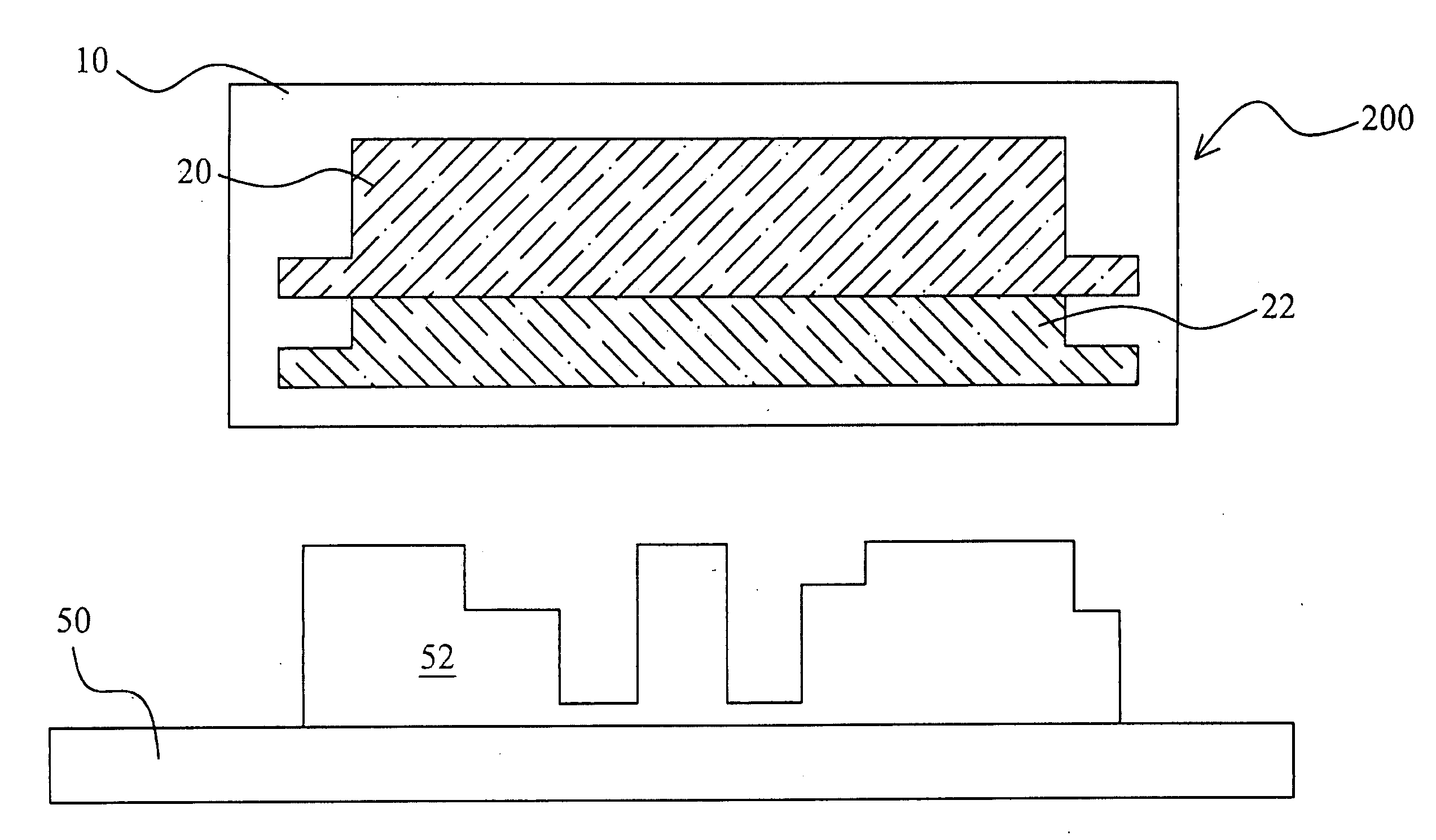
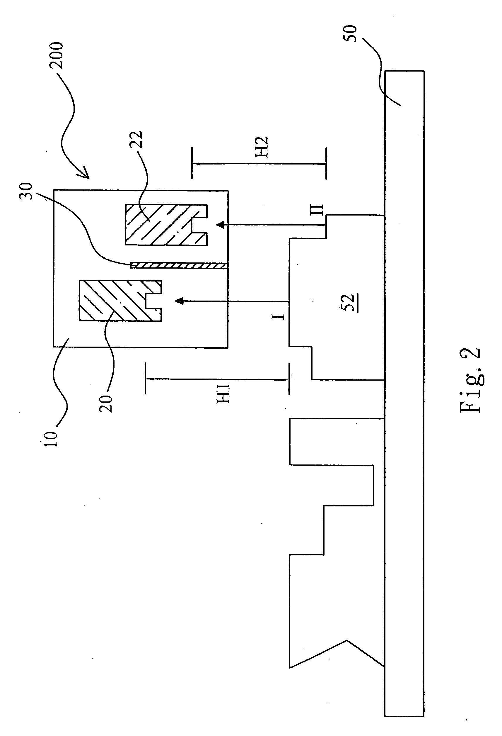
[0019]FIG. 2 is a cross-sectional diagram illustrating an optical carriage structure of an inspection apparatus according to an embodiment of the present invention. The optical carriage 200 structure includes a base 10, a first linear optical sensor array 20, and a second linear optical sensor array 22. The first linear optical sensor array 20 and the second linear optical sensor array 22 are configured at different heights in the base 10. A focal length of the first linear optical sensor array 20 is equal to a vertical distance H1 of the first linear optical sensor array 20 to a first feature I of a sample 52, and a focal length of the second linear optical sensor array 22 is equal to a vertical distance H2 of the second linear optical sensor array 22 to a second feature II of the sample 52.
[0020]In an embodiment, a spacer 30 is configured in the base 10 to separate an optical path of the first linear optical sensor array 20 from an optical path of the second linear optical sensor ...
PUM
 Abstract
Description
Claims
Application Information