
Image forming apparatus

a technology of forming apparatus and fixing unit, which is applied in the direction of electrographic process, electric/magnetic/electromagnetic heating, instruments, etc., can solve the problems of increasing the warm-up time and the entire heat capacity so as to reduce the total heat capacity, reduce the warm-up time of the fixing unit, and save space

Active Publication Date: 2010-02-04
KYOCERA DOCUMENT SOLUTIONS INC
View PDF45 Cites 29 Cited by
  • Summary
  • Abstract
  • Description
  • Claims
  • Application Information

AI Technical Summary

Benefits of technology

The invention aims to reduce the number of components in the heating element of a fixing unit in an image forming apparatus to lower the heat capacity, reduce warm-up time, and save space. This is achieved by using a coil and a first core to form a magnetic path, a second core fixed between the first core and the heating member, and a shielding member that can be moved to switch the position of the magnetic path.

Problems solved by technology

In the first prior art arrangement, the magnetic member should have a large movable range, so that this arrangement has a problem that the entirety of the fixing unit becomes unnecessarily large.
Therefore, if some kind of component is mounted inside the heating roller, it is necessary to increase the Curie temperature of the heating roller and, in addition, there arises a problem that the provision of a large-sized component having a large heat capacity within the heating roller causes an increase in warm-up time thereof.

Method used


Image

  • Image forming apparatus
  • Image forming apparatus
  • Image forming apparatus

Examples


Embodiment Construction

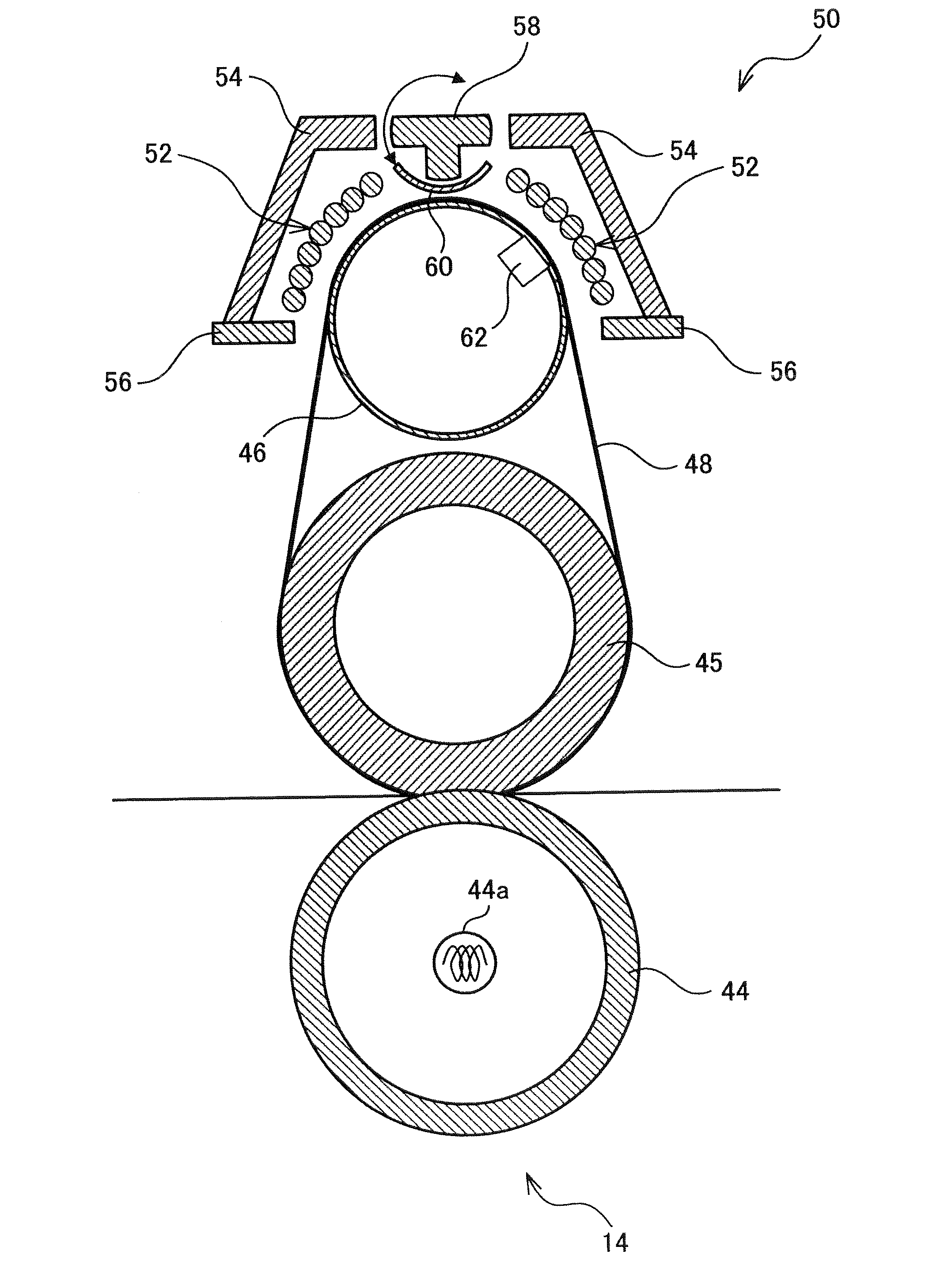
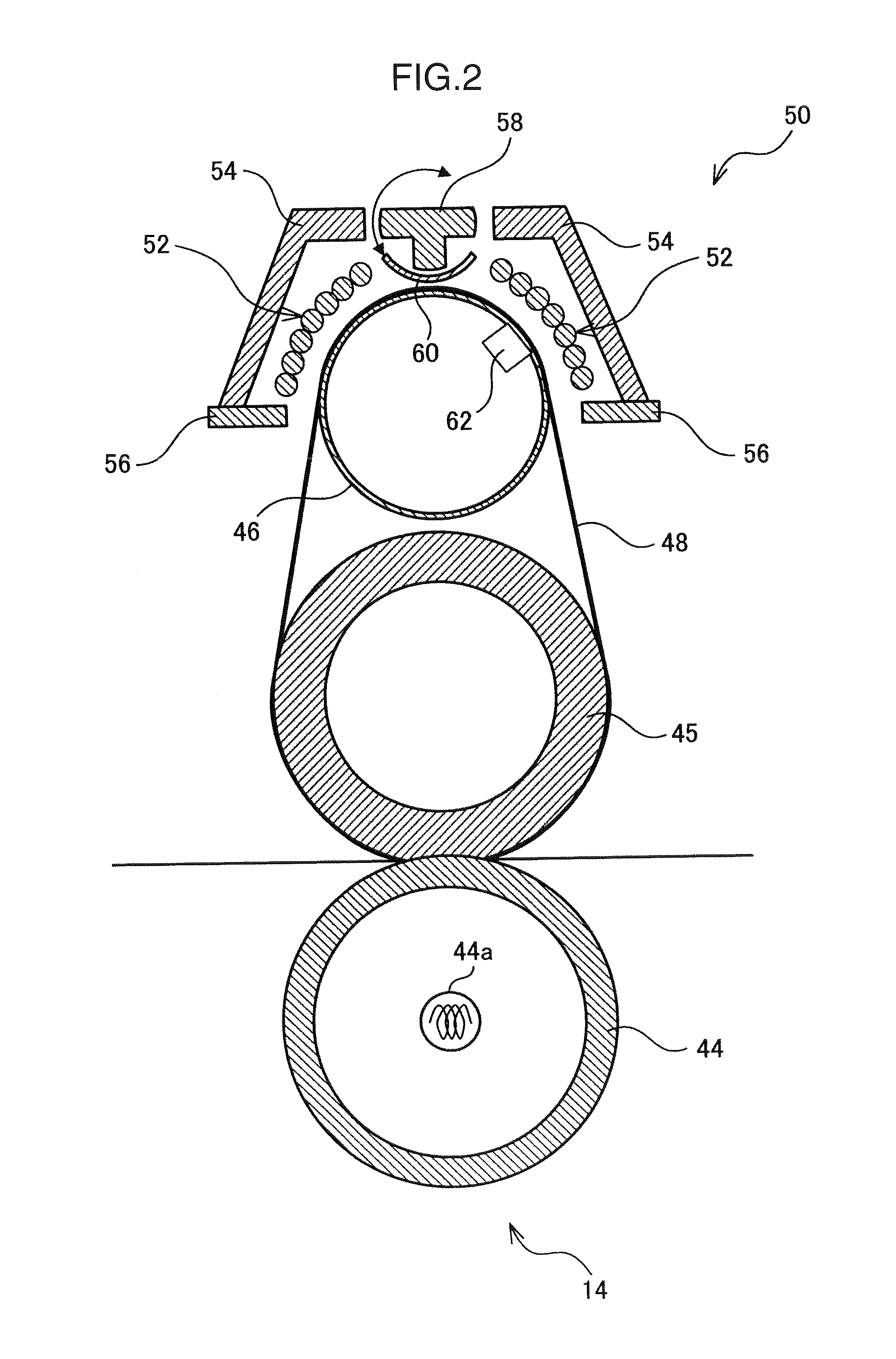
[0034]Now, a preferred embodiment of the invention is described in detail with reference to the accompanying drawings.

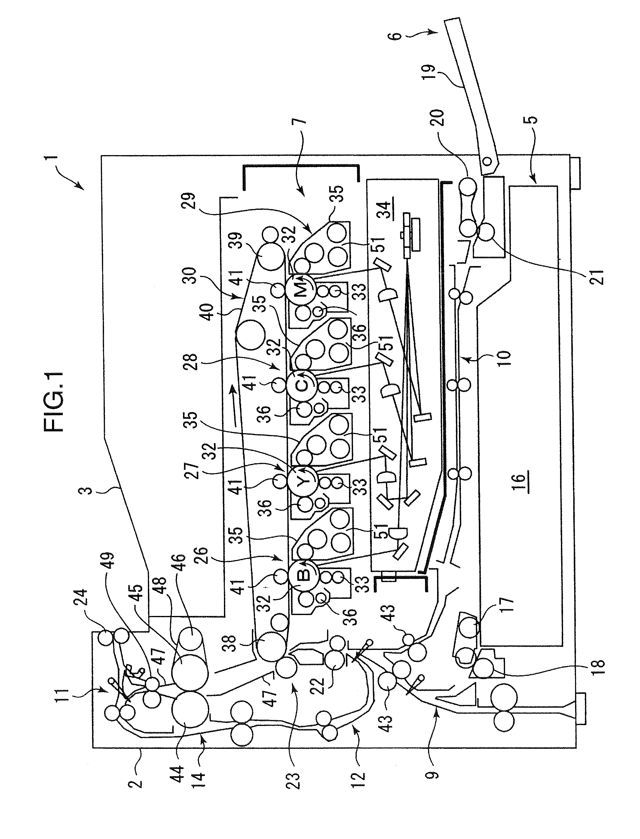
[0035]FIG. 1 is a schematic cross-sectional diagram showing the structure of an image forming apparatus 1 according to the preferred embodiment of the invention. The image forming apparatus 1 may be a printer, a copying machine, a facsimile machine or a hybrid apparatus thereof which are configured to perform printing operation by forming a toner image based on externally input image information, for instance, and transferring the toner image to a surface of a printing medium like a sheet of paper.

[0036]The image forming apparatus 1 shown in FIG. 1 is a tandem-type color printer, for example. The image forming apparatus 1 includes a generally boxlike apparatus body 2 incorporating a print engine for forming (printing) a color image on a sheet and a sheet output portion (output tray) 3 arranged at the top of the apparatus body 2 where the sheet carrying the printed co...


PUM


Abstract

A fixing unit of an image forming apparatus includes a coil arranged along an outer surface of the heating member and generating a magnetic field, a first core arranged opposite the heating member with respect to the coil and forming a magnetic path, a second core so fixed between the first core and the heating member with respect to a direction in which the coil generates the magnetic field, as to form the magnetic path together with the first core, a shielding member positioned outward of the second core and shielding the magnetism in the magnetic path, and a magnetism adjusting unit moving the shielding member outward of the second core to switch the position of the shielding member between a shielding position where the shielding member shields the pass of the magnetism and a retracted position where the shielding member permits the pass of the magnetism.

Description

BACKGROUND OF THE INVENTION[0001]1. Field of the Invention[0002]The present invention relates to an image forming apparatus including a fixing unit which is configured to fix a toner image to a sheet by fusing the unfixed toner while the sheet is passed through a nip between a pair of heated rollers or between a heating belt and a roller.[0003]2. Description of the Related Art[0004]In the aforementioned kind of image forming apparatus, fixing belt systems attract attention due to growing demand for a reduction in warm-up time of a fixing unit and energy savings in recent years. This is because a fixing belt has a low heat capacity as mentioned in Japanese Unexamined Patent Publication No. 6-318001, for example. Also attracting attention recently is electromagnetic induction heating (IH) technology which offers a high-speed, high-efficiency heating capability. Today, products developed by using a combination of the IH technology and belt systems for achieving energy savings in a proc...

Claims


Application Information

Patent Timeline
Patent Type & Authority Applications(United States)
IPC IPC(8): G03G15/20
CPCG03G15/2064G03G15/2053G03G2215/2032
Inventor NANJO, YUZURUASARI, TAMAMI
Owner KYOCERA DOCUMENT SOLUTIONS INC
Learn More