Honing feed system and method employing rapid tool advancement and feed force signal conditioning

a technology of rapid tool advancement and signal conditioning, which is applied in the direction of process control, process control, instruments, etc., can solve the problems of system waste cycle time, machine hone air and/or fixture damage, system could not achieve the initial condition of abrasive repeatability, and the bore geometry is maintained

Active Publication Date: 2010-02-04
SUNNEN PROD
View PDF18 Cites 21 Cited by
  • Summary
  • Abstract
  • Description
  • Claims
  • Application Information

AI Technical Summary

Benefits of technology

[0012]What is disclosed is a honing feed system and method of rapidly advancing a honing tool such the abrasives makes contact with the bore surface at a fast rate, without risking damage to the tool, workpiece, honing machine, or operator, while still maintaining bore geometry, so as to achieve at least one of the objectives sought above. In particular, the system and method of the invention provide a set of conditions that will optimize the cutting action of a honing element of a tool, namely, the attritive, chemical, and fracture wear properties thereof, such that the abrasive grit size, concentration, and type in concert with morphology of the carrier material as a function of material removed can be adjusted or selected. Further, the invention allows for dressing of the abrasive surface of a honing tool in a manner that assures a repeatable initial condition of the abrasive as a honing cycle commences.

Problems solved by technology

If the system expands the tool too far or too fast it risks the chance that the abrasive will impact the workpiece or bore surface with too much force and thus damage the tool and / or fixture.
If the system doesn't expand the tool far enough such that the abrasive does not touch the bore surface, or if it expands too slowly, then the machine will hone air and unnecessarily increase the honing cycle time.
One basic disadvantage of this method comes up if the starting diameter of the un-honed work piece varies from work piece to work piece.
Under these conditions the system could still waste cycle time by honing air between the positions that the tool had rapidly expanded out to, to the actual position of the bore wall.
However, if the constant rate system is in control, then there is no means to measure feed force or to correct bore errors caused by variances in feed force.
Also, it is not possible to select the slower system when it is desirable to do so, e.g. to improve bore geometry at the end of the honing cycle.
However, this system includes no means to measure feed force or to correct bore errors caused by variances in feed force.
Also, it is not possible to select the controlled force system other than for the initial rapid expansion of the stones.
However, this includes no means to measure feed force or to correct bore errors caused by variances in feed force.
The torque limit of the motor is roughly equivalent to a limit on feed force, although mechanical inefficiencies limit the accuracy of using of torque limits as feed force limits.
This system also does not include a means to measure feed force or to correct bore errors caused by variances in feed force.
There also appears to be no means to control the honing feed to a desired feed force apart from merely preventing the force from exceeding some limit.
In such a system, feed force is inferred by measurement of hydraulic pressure and subject to errors such as that induced from frictional forces between the hydraulic piston and its bore.
In a limited way this compensates for errors caused by the elasticity of the workpiece and the feed system components, but as the compensation is a static correction based on force measurements in the previous workpiece, it describes no means to dynamically correct for variations encountered with the workpiece currently being honed.
However, in most applications, this assumption cannot be made reliably.
Also, this method makes no suggestion that honing feed force can be controlled throughout the honing cycle.

Method used


Image

  • Honing feed system and method employing rapid tool advancement and feed force signal conditioning
  • Honing feed system and method employing rapid tool advancement and feed force signal conditioning
  • Honing feed system and method employing rapid tool advancement and feed force signal conditioning

Examples


Embodiment Construction

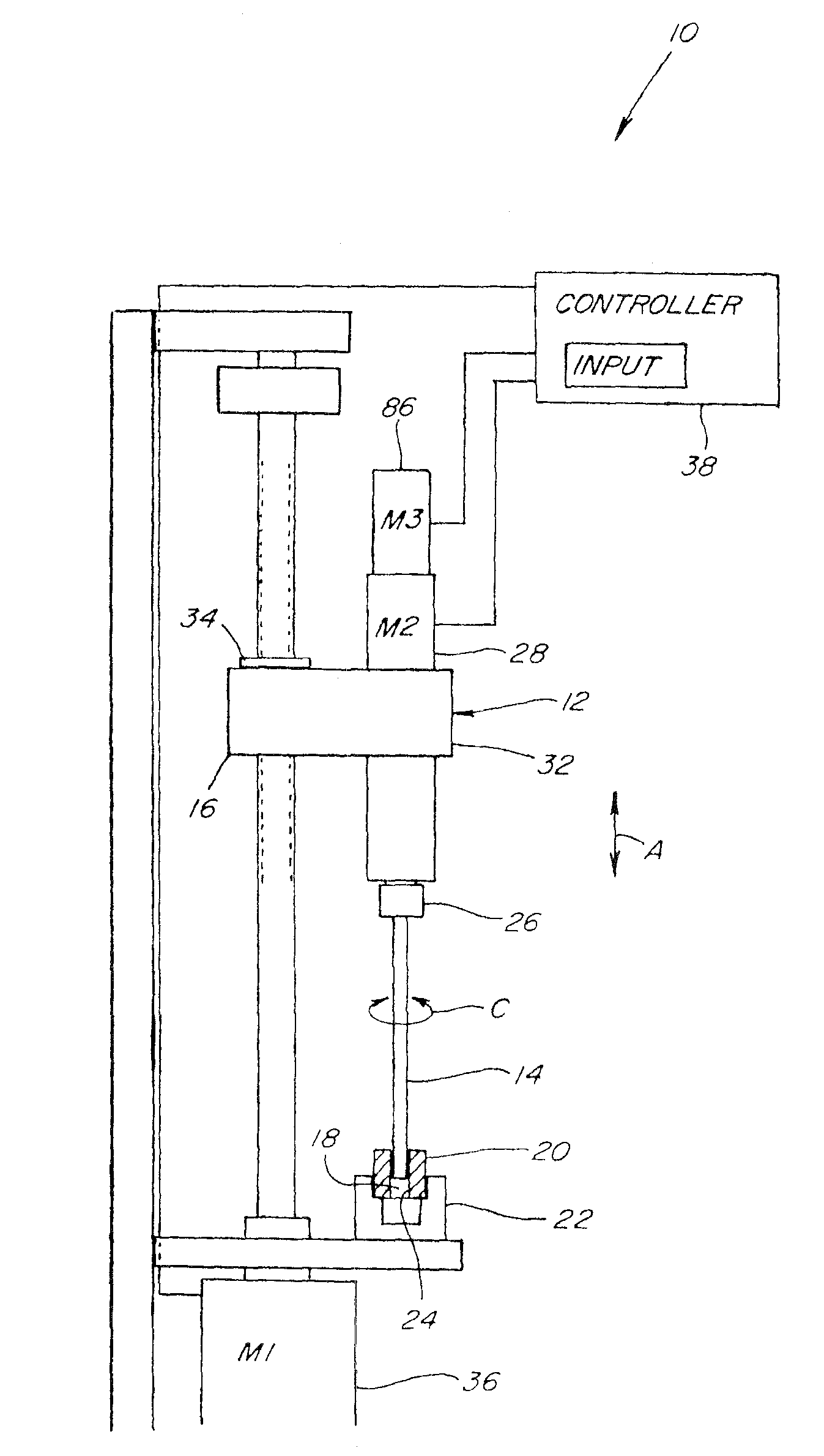
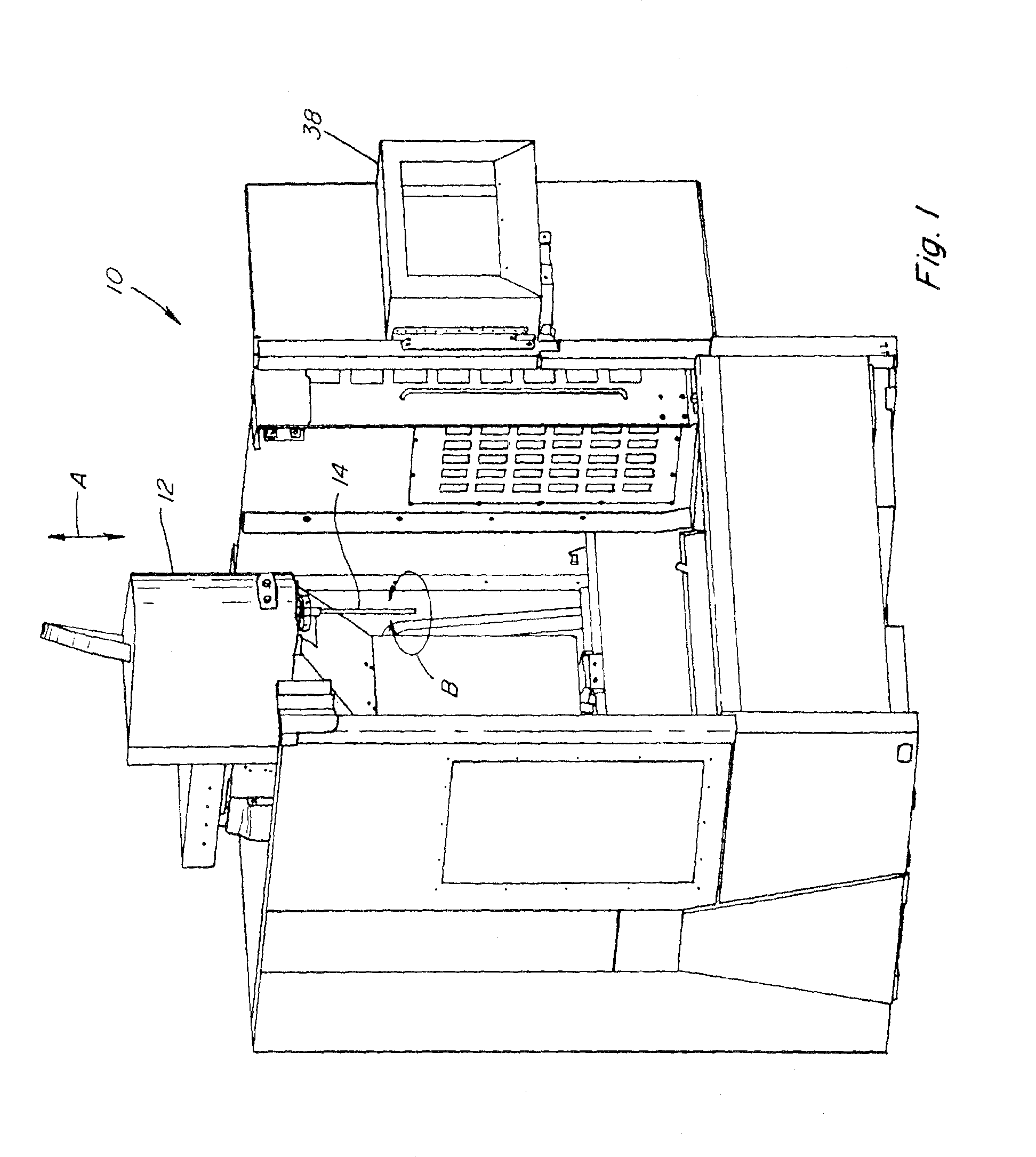
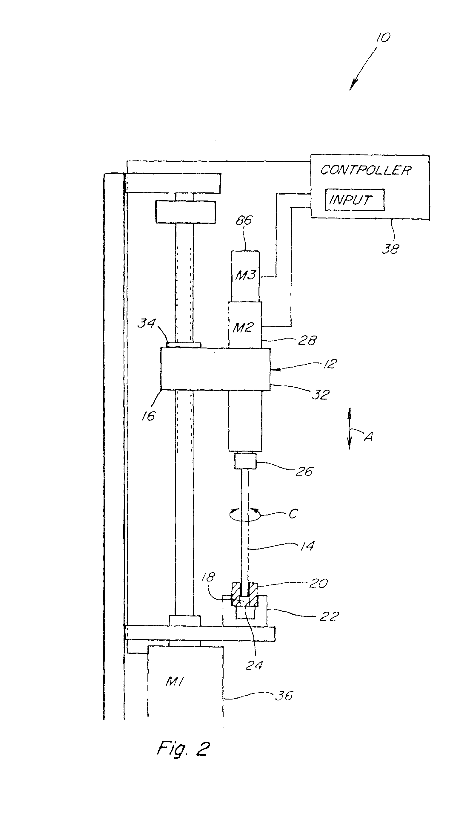
[0040]Referring now to the drawings wherein a preferred embodiment of a feed system and method of operation thereof is shown, in FIG. 1, a representative computer controlled honing machine 10 is shown including aspects of the feed system according to the present invention. Honing machine 10 generally includes a spindle carriage 12 which is movable in a reciprocating stroking action, denoted by arrow A, by a linear motion system such as a conventional motor driven cam linkage mechanism, or a ball screw, roller screw, linear servomotor, rack and pinion, hydraulic cylinder, chain, or belt, under control of a process based main controller 38. Here, carriage 12 is shown supported for reciprocal stroking action in a vertical direction, but it should be understood that stroking in other directions is also contemplated under the present invention. Spindle carriage 12 includes a honing tool 14, which can be of conventional or new construction and operation, generally including an elongate ma...


PUM

PropertyMeasurementUnit
feed forceaaaaaaaaaa
feed rateaaaaaaaaaa
linear forceaaaaaaaaaa

Abstract

The honing feed system and method utilizes feedback from various sources during rapid feeding of the honing tool while rotating and stroking, to detect initial contact with a bore surface, to slow the feed to a normal honing rate, involving conditioning the feedback signals to eliminate noise factors such as the stroking movement and forces generated to rotate and feed the tool unopposed.

Description

[0001]This application is a continuation-in-part of co-pending patent application Ser. No. 12 / 119,145, filed May 12, 2008, which application is a division of patent application Ser. No. 11 / 596,836, filed Nov. 17, 2006, now U.S. Pat. No. 7,371,149, issued May 13, 2008, and also claims the benefit of U.S. Provisional Application No. 60 / 607,742, filed Sep. 7, 2004.TECHNICAL FIELD [0002]The present invention is directed to a honing feed system and method, and more particularly, which utilizes feedback from various sources to control the feed including to condition the feedback signals to determine precisely the occurrence of contact between the honing tool and workpiece or bore surface, including with the tool rotating at full honing speeds and stroking.BACKGROUND ART [0003]Existing honing machines normally control the beginning of the honing cycle wherein the feed system is rapidly expanding the tool to a specific feed position. If the system expands the tool too far or too fast it ris...

Claims


Application Information

Patent Timeline
Patent Type & Authority Applications(United States)
IPC IPC(8): B24B51/00B24B49/16
CPCB23Q15/225B23Q17/2233B24B33/02B24B47/20B24B49/16G05B19/404G05B2219/49356G05B2219/45237G05B2219/49079G05B2219/49099G05B2219/49114G05B2219/49182G05B2219/41109
Inventor CLOUTIER, DANIEL R.HOTH, TIMOTHY P.JACOBSMEYER, RUSSELL L.NIKRANT, MICHAEL J.
Owner SUNNEN PROD
Why Eureka
Try Eureka