Control surface failsafe drop link

a control surface and drop link technology, applied in the direction of wing adjustment, aircraft transmission means, wings, etc., can solve the problem of detachment of the control surface from the structure of the aircraft, and achieve the effect of saving weigh

Active Publication Date: 2010-02-11
AIRBUS OPERATIONS LTD
View PDF10 Cites 26 Cited by
  • Summary
  • Abstract
  • Description
  • Claims
  • Application Information

AI Technical Summary

Benefits of technology

[0019]Thus the construction according to various embodiments of the invention obviates the need for separate failsafe hinges mounted between the control surface and the corresponding part of the aircraft structure and permits the removal of the failsafe attachment hardware, thus allowing a significant weight saving to be achieved.
[0020]The drop link may include a fa

Problems solved by technology

Such a failure would normally result in the detachment o

Method used


Image

  • Control surface failsafe drop link
  • Control surface failsafe drop link
  • Control surface failsafe drop link

Examples


Embodiment Construction

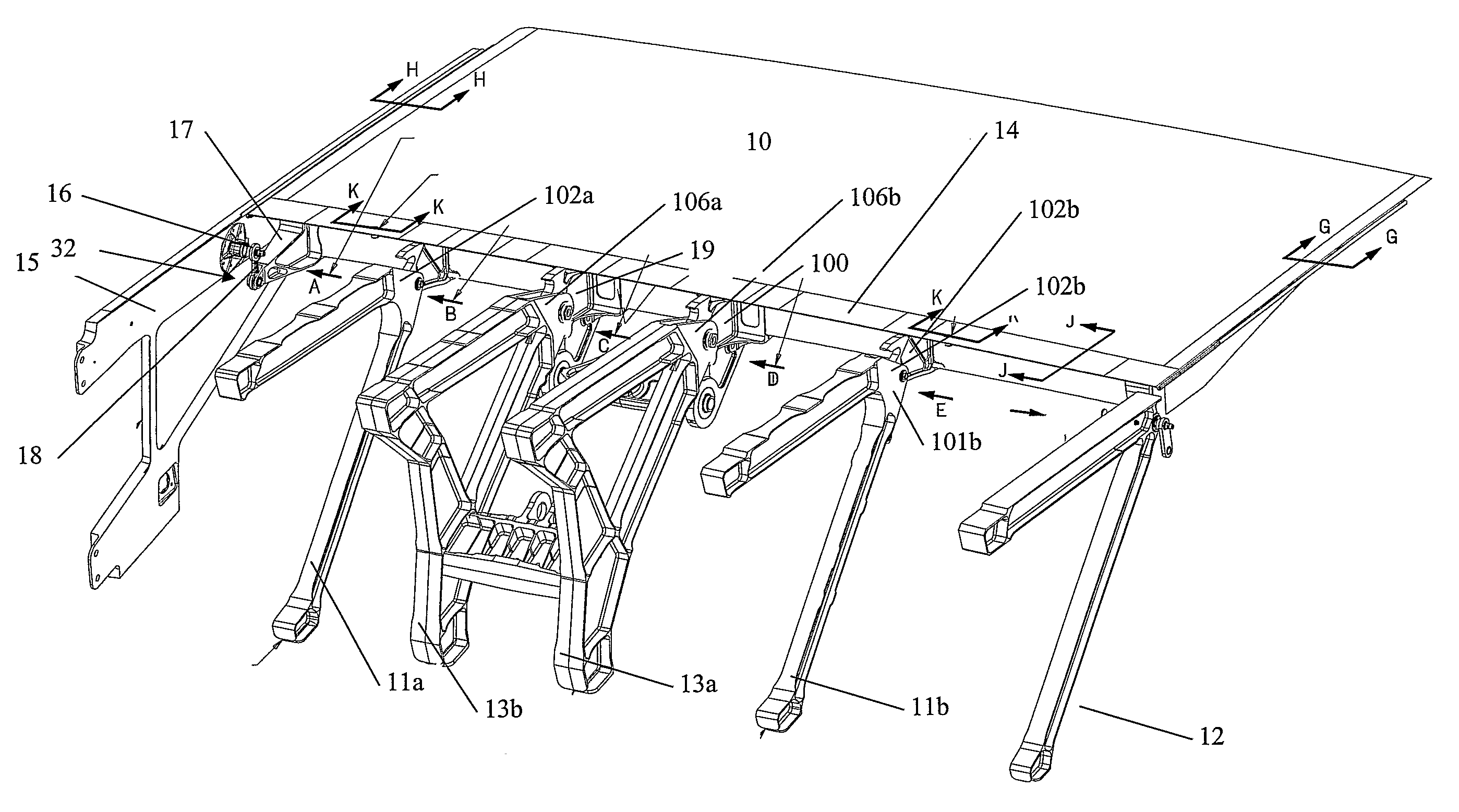
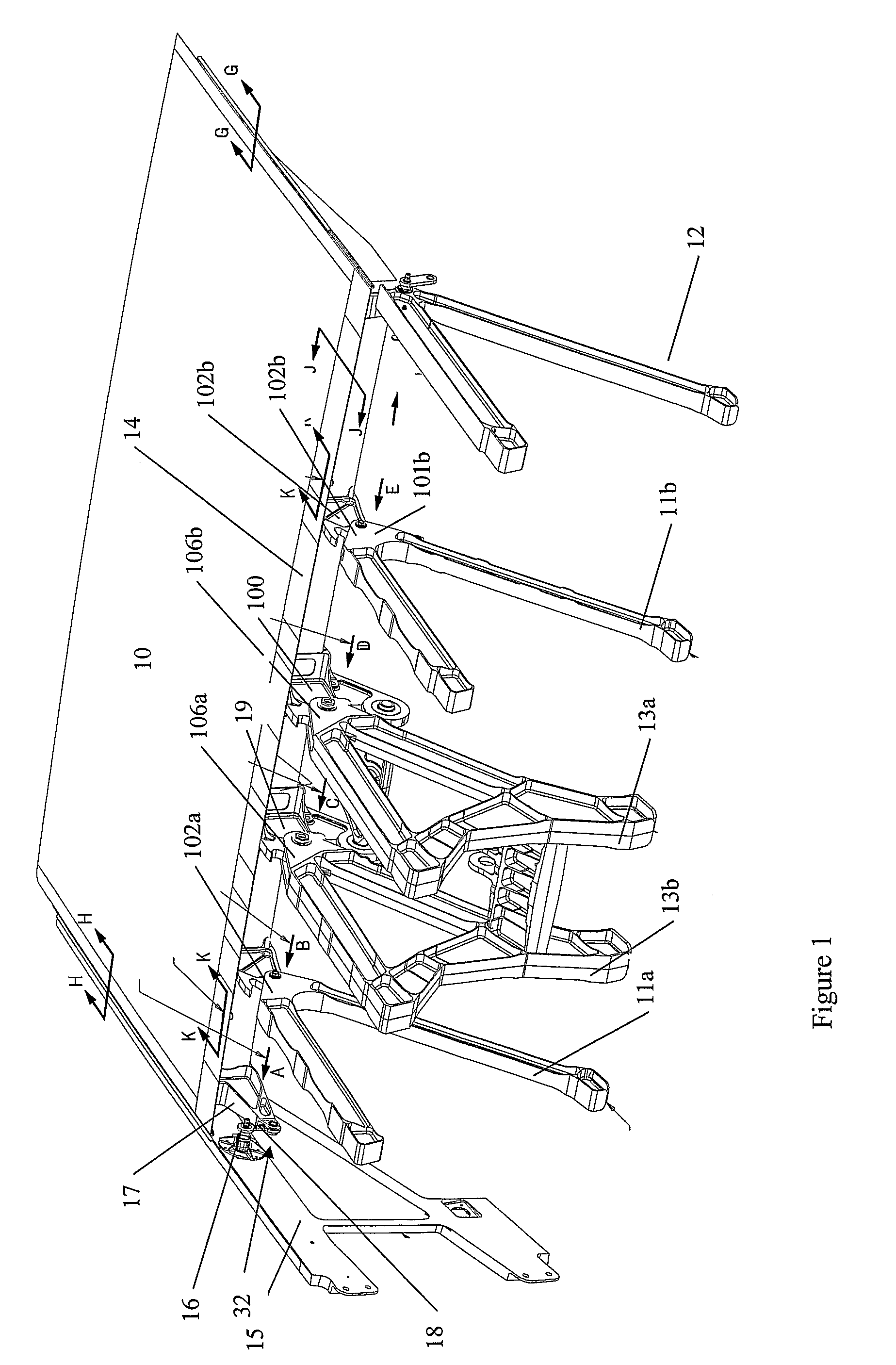
[0036]The specific description, which follows, relates to a spoiler installation on a wing. However, as noted above, the invention may be applied to other control surface installations with appropriate modifications.

[0037]FIG. 3 illustrates a spoiler failsafe hinge drop link construction and installation in accordance with an embodiment of the invention. Referring to FIG. 3, a spoiler 10 is attached to spoiler ribs 31a and 31b with are mounted on the trailing edge of a wing box, the rear spar of which is indicated by the numeral 35. Conventional spoiler extension / retraction is provided by means of primary hinges 35a and 35b. However, by comparison with the layout shown in FIG. 1, there are no spoiler failsafe hinges mounted on the spoilers adjacent the spoiler failsafe hinge ribs 30a and 30b (these ribs being shown to illustrate the conventional location of the failsafe hinges).

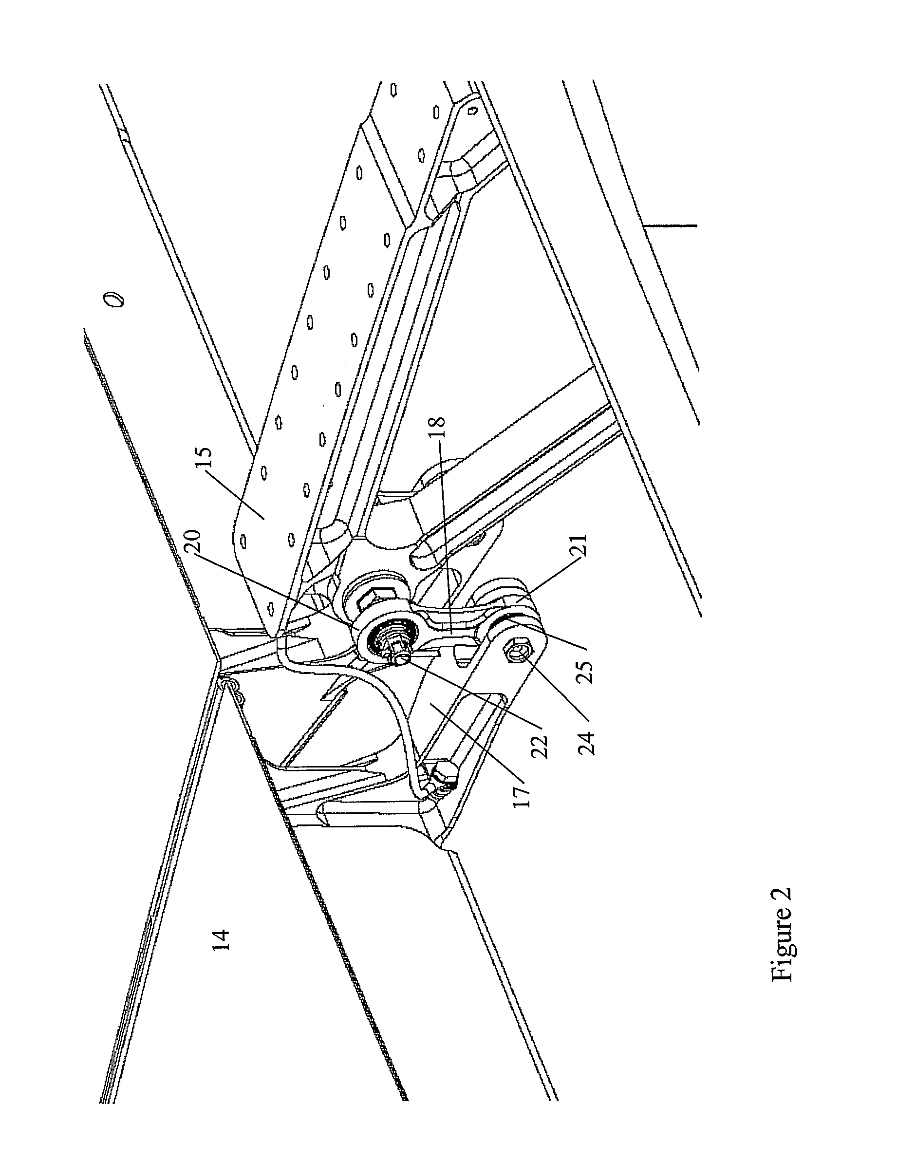
[0038]Spoiler failsafe hinge drop link configurations 32 are located at the ends of the spoilers where the...


PUM


Abstract

An aircraft control surface failsafe hinge configuration is disclosed. The arrangement comprises a drop link configuration which is adapted to attach a control surface to an aircraft structure where the drop link additionally incorporates a failsafe hinge means which provides a backup hinge connection between the control surface and the aircraft structure to which it is attached. The improved failsafe hinge construction may be applied to any aircraft control surface such as an aileron, elevator, vertical tail plane and the like.

Description

TECHNICAL FIELD[0001]The present invention relates to methods and apparatus for connecting control surfaces to aircraft structures. More particularly, although not exclusively, the invention relates to methods and apparatus for connecting spoilers to wing structures. The invention further relates to failsafe systems for control surface connection arrangements between, for example, spoilers and wing structures.BACKGROUND ART[0002]Conventionally, on large transport aircraft aerodynamic control surfaces, such as spoilers, are attached to a corresponding aircraft structure by means of primary hinges, failsafe hinges and drop links. Specific construction techniques have been developed for the installation of such control surfaces, specifically to provide the desired operating and failsafe characteristics of the aircraft component.[0003]The following description is specifically provided in the context of providing failsafe functionality to spoiler installations. However, it is to be under...

Claims


Application Information

Patent Timeline
IPC IPC(8): B64C13/28B64C9/02
CPCY02T50/44B64C9/02Y02T50/40
Inventor MAURAN, GUYBLADES, PAULBURNESS, RICHARD JOHN HENRY
Owner AIRBUS OPERATIONS LTD
Why Eureka
Try Eureka