
Input device with display function

a technology of input device and display function, which is applied in the direction of static indicating device, manufacturing tool, instruments, etc., can solve problems such as appearance problems, and achieve the effect of convenient and precise performan

Active Publication Date: 2010-02-11
WACOM CO LTD
View PDF15 Cites 23 Cited by
  • Summary
  • Abstract
  • Description
  • Claims
  • Application Information

AI Technical Summary

Benefits of technology

[0017]Accordingly, it is an object of the present invention to provide an input device with display function, which has a high degree of freedom in design, excellent operability, and in which position alignment for assembling components of the display module can be simply performed.
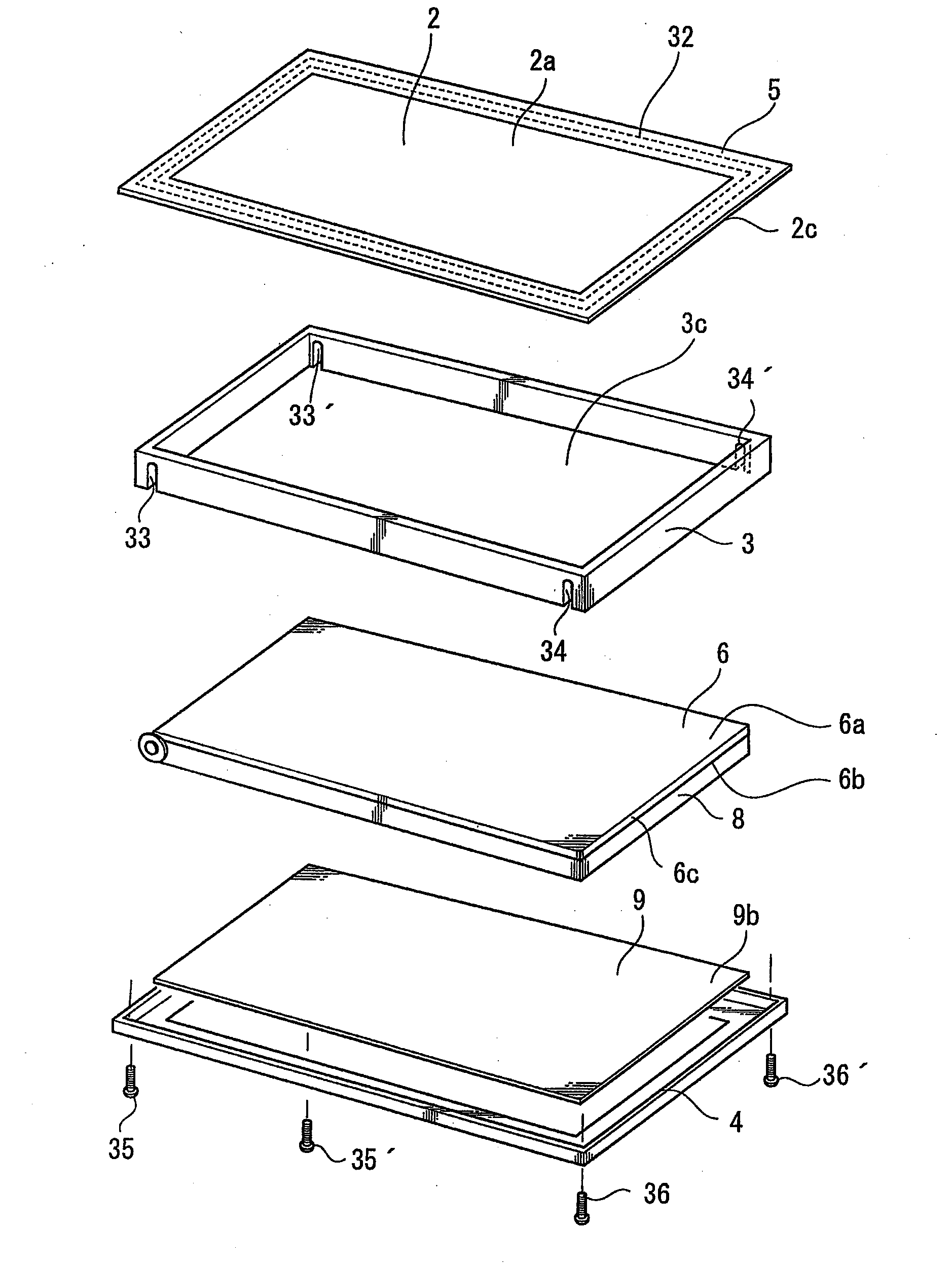
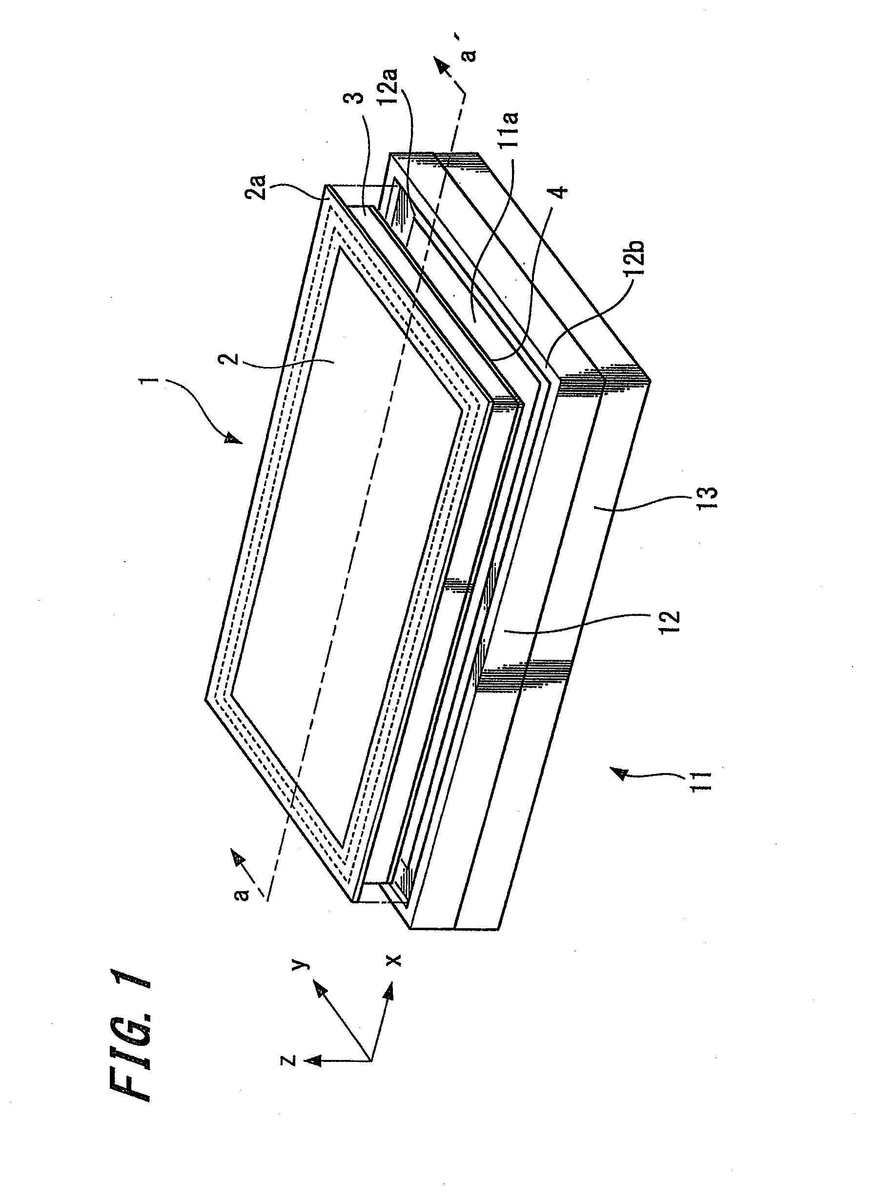
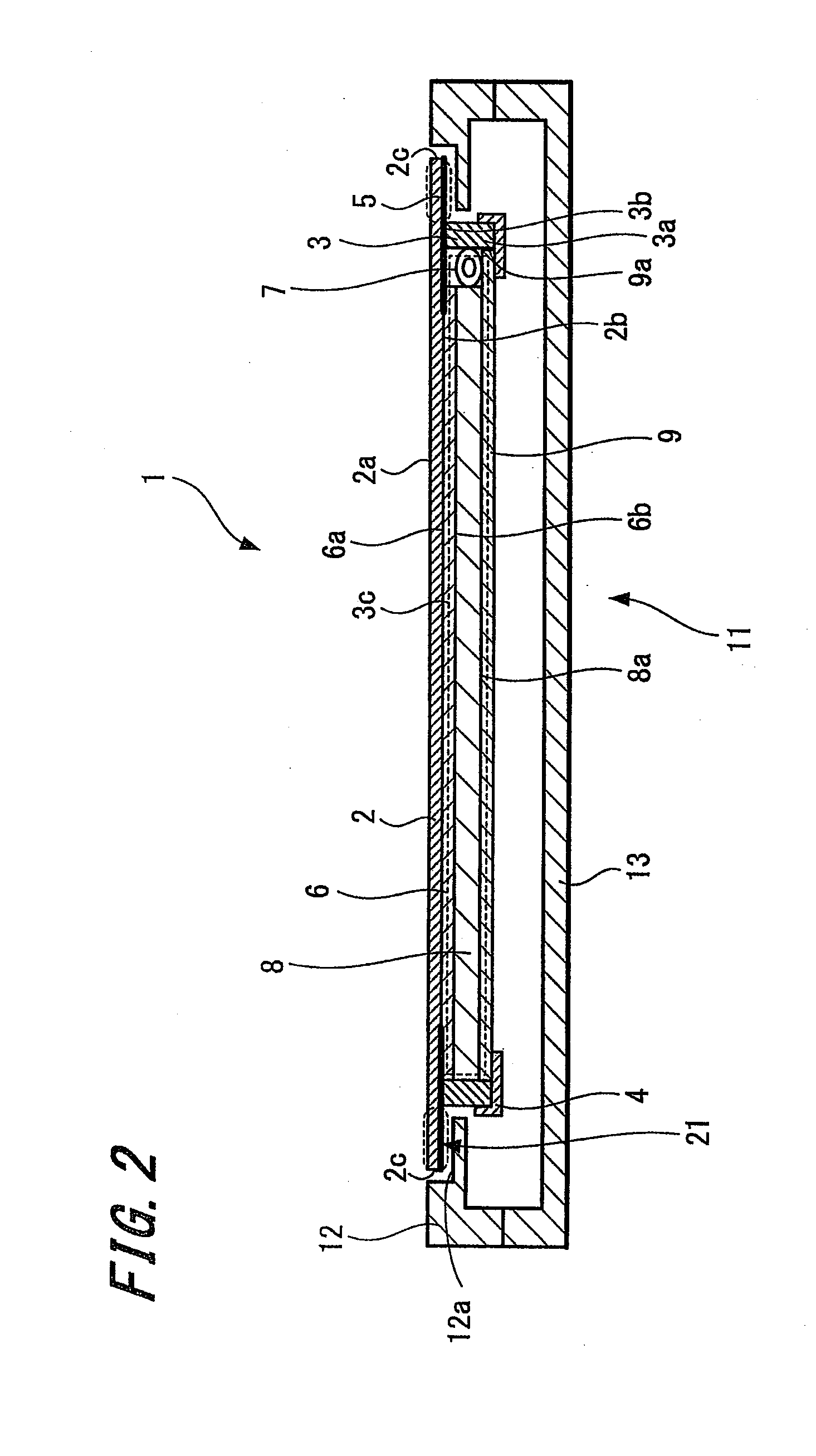
[0021]According to the present invention, since the frame is provided on the lower surface side of the transparent panel to house and secure therein the flat panel display unit and the flat sensor, positioning and assembly of the transparent panel, the flat panel display unit, and the flat sensor can be easily and precisely performed.

Problems solved by technology

In the case of an ordinary liquid crystal display device with no input function, even if the offset or the gap 152 is generated, it will cause no problem in function, though it does cause some problems in appearance.

Method used


Image

  • Input device with display function
  • Input device with display function
  • Input device with display function

Examples


examples of application

[0090]Examples of applying the liquid crystal module according to the aforesaid embodiments to various electronic devices will be described below with reference to FIGS. 9 to 11.

[0091]FIG. 9 shows an example of applying the liquid crystal module to a general-purpose personal computer.

[0092]In the personal computer shown in FIG. 9, a liquid crystal module 93 according to the aforesaid embodiments is incorporated into a display 92 connected to a computer main body 91. With such a configuration, in order to perform a coordinate input operation on the personal computer shown in FIG. 9, the user uses a stylus pen 94 to draw lines or points on the screen of the liquid crystal module 93.

[0093]Note that, although FIG. 9 shows an example in which the personal computer and the display 92 are separated from each other, the present invention may also be applied to a computer in which the display 92 and the main body 91 are integrated, such as a laptop computer.

[0094]FIG. 10 shows an example of ...


PUM

PropertyMeasurementUnit
transparentaaaaaaaaaa
thicknessaaaaaaaaaa
shapeaaaaaaaaaa

Abstract

A liquid crystal module (1) includes a transparent panel (2) having a frame (3) projecting substantially perpendicularly from one surface thereof. The module also includes a flat panel display unit having a liquid crystal cell (6), a liquid crystal back light (7), and a liquid crystal back light unit (8), for example. The module further includes a flat sensor (9), such as a thin digitizer (a coordinate position inputting sensor). The frame is configured such that the flat panel display unit and the flat sensor can be readily housed and secured within a housing portion inside the frame.

Description

CROSS REFERENCES TO RELATED APPLICATIONS[0001]The present application claims priority under 35 U.S.C.§119 from Japanese Patent Application JP 2008-043581, filed in the Japanese Patent Office on Feb. 25, 2008, the entire contents of which are incorporated herein by reference.BACKGROUND OF THE INVENTION[0002]1. Field of the Invention[0003]The present invention relates to an input device with display function for performing input operation to a digitizer (a coordinate position inputting sensor) based on, for example, an electromagnetic resonance technology.[0004]2. Description of the Related Art[0005]In recent years, there has been proposed an input device with liquid crystal display function to be applied to an electronic device such as a personal computer, a PDA (personal digital assistant) or the like. There also has been proposed a position detecting device in which a shield plate is used (see Japanese Unexamined Patent Application Publication No. 2005-275381 and Japanese Unexamine...

Claims


Application Information

Patent Timeline
Patent Type & Authority Applications(United States)
IPC IPC(8): G06F3/044G06F3/041B23P11/00
CPCY10T29/49826G06F3/041G06F1/1601G06F3/0412G02F1/13338G06F3/04164G06F3/03547G06F1/1643
Inventor HORIE, TOSHIHIKO
Owner WACOM CO LTD
Learn More