Optical apparatus

Inactive Publication Date: 2010-02-11
CANON KK
View PDF3 Cites 2 Cited by
  • Summary
  • Abstract
  • Description
  • Claims
  • Application Information

AI Technical Summary

Benefits of technology

[0016]Since an urging force for urging the moving members toward the interlocking movement member that is moved along the optical axis

Problems solved by technology

Because of this complicated cam driving mechanism, operating noise, such as tapping noise of gears that constitute the cam driving mechanism, increases.
Hence, the cam driving mechanism is not suitable for movie t

Method used


Image

  • Optical apparatus
  • Optical apparatus
  • Optical apparatus

Examples


first embodiment

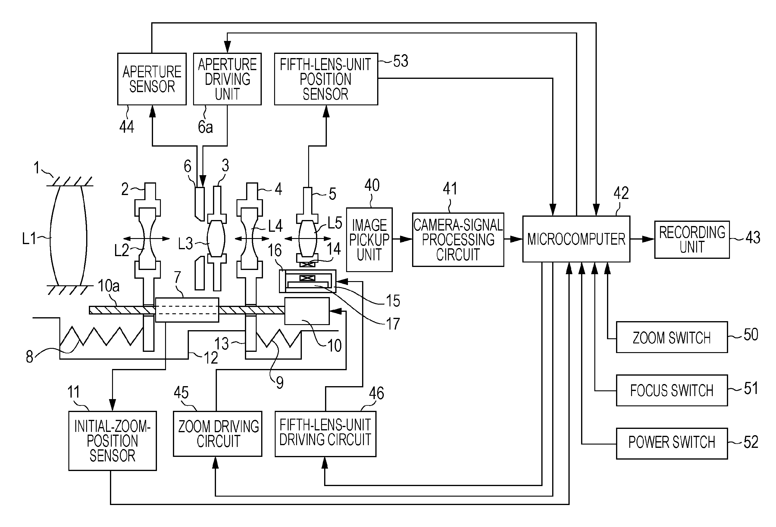
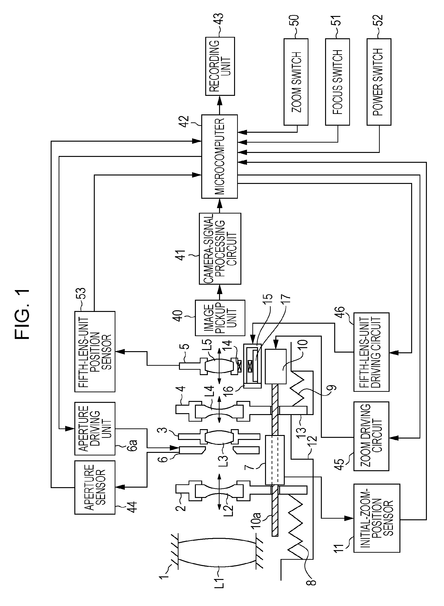
[0027]FIG. 1 shows a configuration of an optical apparatus according to a first embodiment of the present invention, which apparatus is used in a digital still camera, a video camera, or an interchangeable lens.

[0028]In the first embodiment, an imaging optical system includes, in order from an object side to an image side, a first lens unit, a second lens unit, a third lens unit, a fourth lens unit, and a fifth lens unit.

[0029]Referring to FIG. 1, a first lens unit L1 has a positive refractive power, and does not move during zooming.

[0030]A second lens unit L2 has a negative refractive power, and serves as a first zoom lens unit that moves along the optical axis for zooming.

[0031]A third lens unit L3 has a positive refractive power, and does not move during zooming.

[0032]A fourth lens unit L4 has a negative refractive power, and serves as a second zoom lens unit that moves along the optical axis for zooming.

[0033]A fifth lens unit L5 has a positive refractive power, and moves along ...

second embodiment

[0088]In an optical apparatus according to a second embodiment, the dimensions at a middle position (where switching between a second lens unit L2 and a fourth lens unit L4 is made) are changed, as shown in FIG. 6.

[0089]Other structures of the optical apparatus are the same as those adopted in the first embodiment.

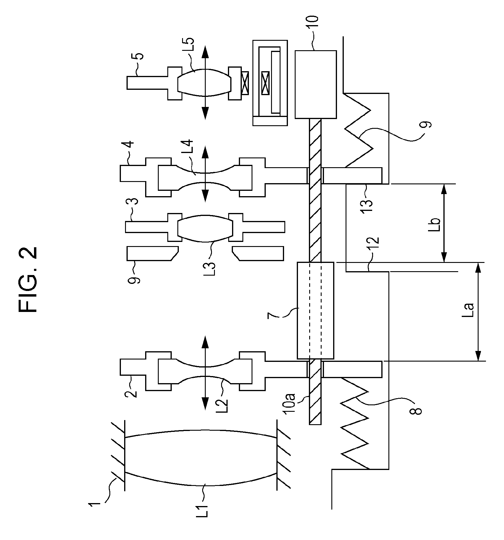
[0090]In the second embodiment, a lead screw 10a serving as a feed screw is also provided to be coaxial with a rotor in a zoom motor and parallel to the optical axis.

[0091]In other words, a length La of a rack member 7 along the optical axis (distance between a portion of the rack member 7 in contact with a first moving member 2 and a portion in contact with a second moving member 4) is set to be smaller than a distance Lb from a first regulating portion 12 to a second regulating portion 13. This can make two discontinuous zoom ranges.

[0092]To achieve discontinuous zooming, both the first moving member 2 and the second moving member 4 are not in contact with the rack membe...


PUM


Abstract

An optical apparatus includes an optical system in which two zoom lens units perform zooming in different ranges in accordance with a zoom position, and a mechanism for driving the two zoom lens units by a single driving portion. An urging force for urging moving members toward an interlocking movement member that is moved along the optical axis by a feed screw is cut off by regulating portions.

Description

BACKGROUND OF THE INVENTION[0001]1. Field of the Invention[0002]The present invention relates to optical apparatuses capable of zooming. More particularly, the present invention relates to an optical apparatus for image taking and an optical apparatus for observation, for example, a digital still camera, a video camera, or an interchangeable lens.[0003]2. Description of the Related Art[0004]A typical lens apparatus including a plurality of moving lens units adopts a mechanical interlocking mechanism using a cam ring, and a driving portion (actuator) for each of the moving lens units.[0005]Computer zooming is known in which each driving portion (actuator) performs zooming and focusing.[0006]To reduce the cost by sharing the driving portion, there has been proposed a mechanism in a lens apparatus for driving two moving lens units by one actuator.[0007]For example, in a mechanism disclosed in Japanese Patent Laid-Open No. 64-84233, a zoom lens unit and a focus lens unit are driven by a...

Claims


Application Information

Patent Timeline
IPC IPC(8): G02B15/14
CPCG02B15/173G02B7/102G02B15/145121
Inventor TSUZUKI, MASAHIKO
Owner CANON KK
Why Eureka
Try Eureka