Robust Jitter-Free Remote Clock Offset Measuring Method

a remote clock offset and measurement method technology, applied in the field of remote clock offset measurement methods and apparatuses, can solve the problems of limiting accuracy to 10 microseconds or worse, software-only solutions to clock synchronization, and affecting the accuracy of the clock,

Active Publication Date: 2010-02-11
GLOBALFOUNDRIES US INC
View PDF22 Cites 29 Cited by
  • Summary
  • Abstract
  • Description
  • Claims
  • Application Information

AI Technical Summary

Benefits of technology

[0008]The foregoing summary of the various embodiments of the present invention is exemplary and non-limiting. For example, one with ordinary skill in the art will understand that one or

Problems solved by technology

It is widely held that software-only solutions to clock synchronization suffer from inevitable “system noise” (process dispatching, interrupt handling etc.) that limit accuracy to 10

Method used


Image

  • Robust Jitter-Free Remote Clock Offset Measuring Method
  • Robust Jitter-Free Remote Clock Offset Measuring Method
  • Robust Jitter-Free Remote Clock Offset Measuring Method

Examples


Embodiment Construction

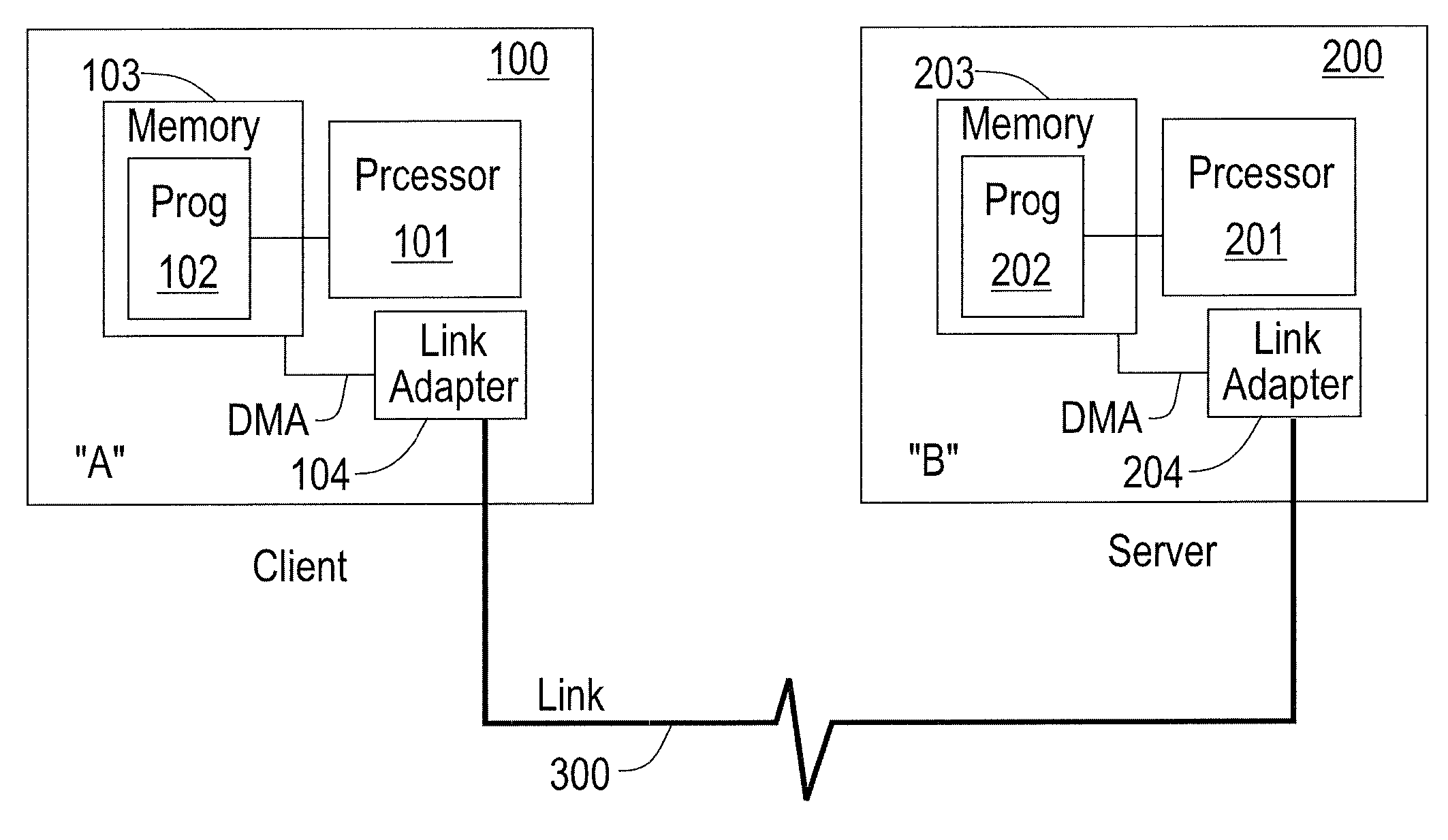
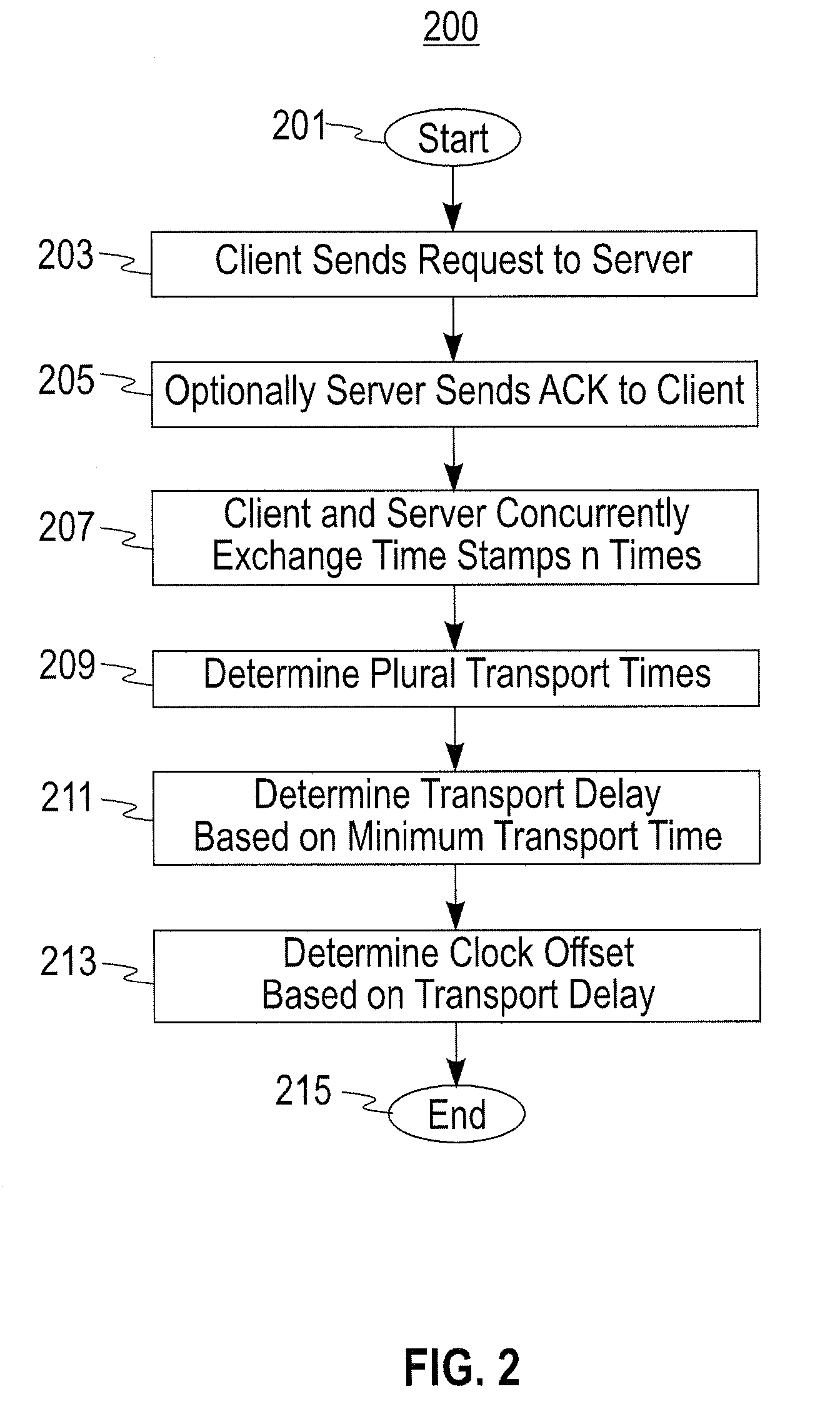
[0017]Briefly, a clock offset between a client and a server is measured as follows:

[0018](a) the client sends a request for a “pingpong exchanger” to the server (who is waiting for this request passively, i.e. not consuming resources).

[0019](b) upon receiving the request of step (a), the server optionally sends an acknowledgement to the client (who is also waiting passively, if this step is used). Whether or not an acknowledgement is sent, the server enters an active wait loop for the client's first pingpong packet.

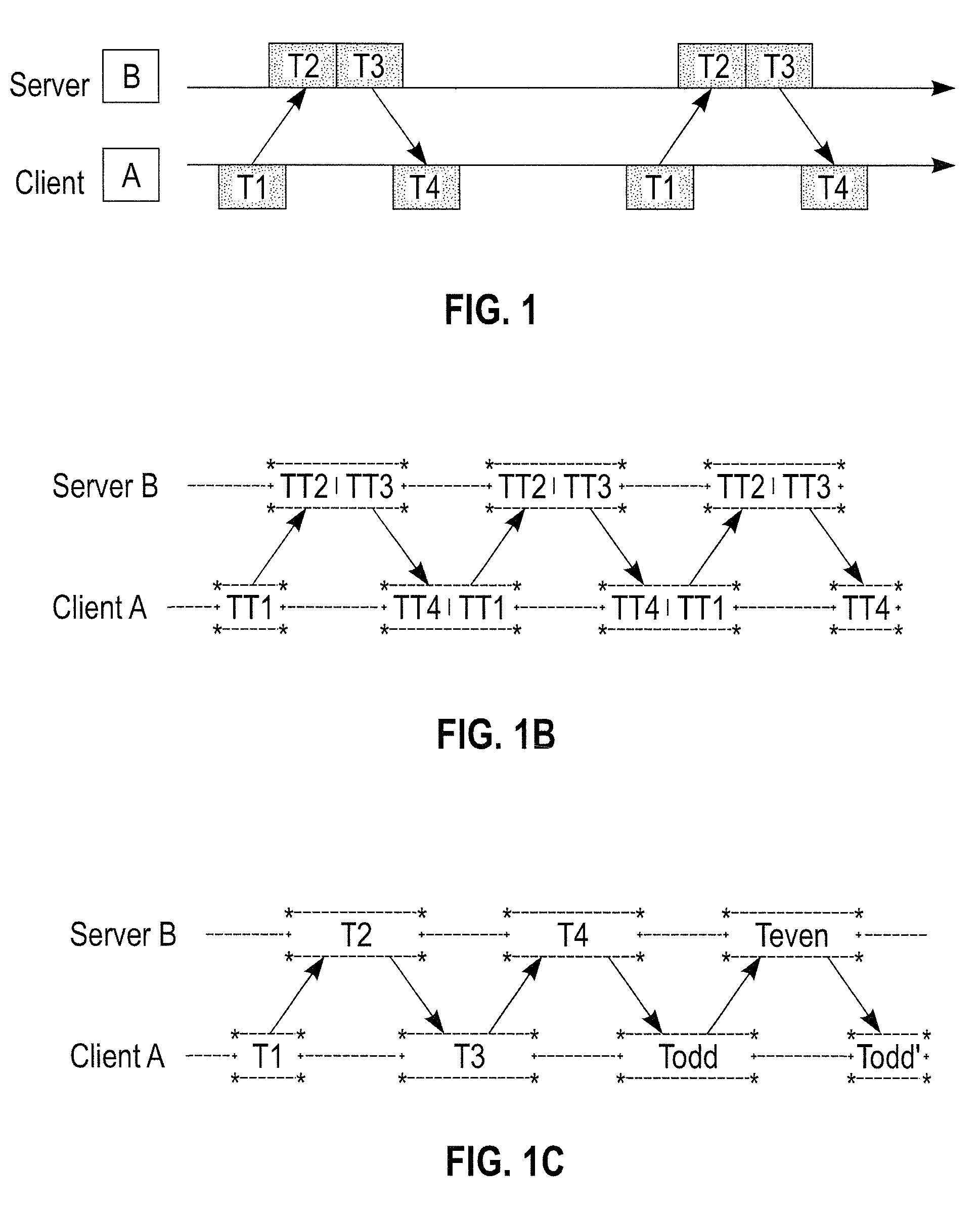
[0020](c) upon the client receiving the acknowledgement of step (b), or immediately after step (a) if step (b) did not involve an acknowledgement, the client starts the pingpong exchange by sending the first pingpong packet to the server and then waiting actively for a reply. Both client and server perform an agreed-upon number of pingpong exchanges. Each pingpong packet includes at least the timestamp at which it was sent.

[0021](d) The apparent forwards and backwards del...


PUM


Abstract

A clock offset between a client and a server is measured by: (a) the client sending a request to the server; (b) upon receiving the request in step (a), the server optionally sending a server acknowledgement to the client; (c) upon the client receiving the server acknowledgement in step (b) or directly, if no acknowledgement was used, each of the client and the server proceeding to concurrently exchange their respective timestamps with each other a multiplicity (n) of times, thus forming a multiplicity (n) of timestamp exchanges; and (d) determining a plurality of apparent forwards and backwards delays based on the multiplicity (n) of timestamp exchanges. The preferred apparent forwards and backwards delays are then selected based on the minimum values (for each direction) determined in (d) above. The clock offset between client and server is then determined based on the preferred apparent forwards and backwards delays.

Description

TECHNICAL FIELD[0001]The present invention generally concerns methods and apparatus for measuring a remote clock offset with very low jitter.BACKGROUND[0002]It is widely held that software-only solutions to clock synchronization suffer from inevitable “system noise” (process dispatching, interrupt handling etc.) that limit accuracy to 10 microseconds or worse. When microsecond-level synchronization is needed, hardware solutions are employed, e.g., network adapters with IEEE 1588 (Precise Time Protocol) support at both ends of the communications link.[0003]As depicted in FIG. 1A, the typical software timestamp exchange has client node A send a timestamp T1 to server node B, which receives it at time T2. Server node B then sends a reply at time T3, and client node A receives it at time T4. T1 and T4 are measured using client node A's clock; T2 and T3 are measured on server node B's clock. From this information the offset between the clocks of client A and server B can be determined—bu...

Claims


Application Information

Patent Timeline
IPC IPC(8): G06F11/30
CPCH04J3/0667H04L43/106H04L43/087H04L43/0858
Inventor FROEHLICH, STEVENHACK, MICHEL H. T.MENG, XIAOQIAOZHANG, LI
Owner GLOBALFOUNDRIES US INC
Why Eureka
Try Eureka