
Control Data Generation Device and Method

a data generation and control technology, applied in the direction of electronic editing digitised analogue information signals, instruments, carrier indicating arrangements, etc., can solve the problem that the prior art technique cannot solve the error problem in a drastic manner, predetermined control, such as level adjustment, would be undesirable to perform on an audio signal, and detection data in a slightly inaccurate manner. problem, to achieve the effect of eliminating positioning errors, effective and efficient utilization of position sensors, and high resolution

Inactive Publication Date: 2010-02-11
YAMAHA CORP
View PDF12 Cites 15 Cited by
  • Summary
  • Abstract
  • Description
  • Claims
  • Application Information

AI Technical Summary

Benefits of technology

[0007]In view of the foregoing, it is an object of the present invention to provide an improved control data generation device and method which can generate appropriate control data, causing no odd feeling, by effectively eliminating a positioning error, produced at the time of automatic operation of the operation member, in response to manual operation of the operation member performed immediately after the automatic operation and thereby permits effective and efficient utilization of the position sensor having a high resolution.
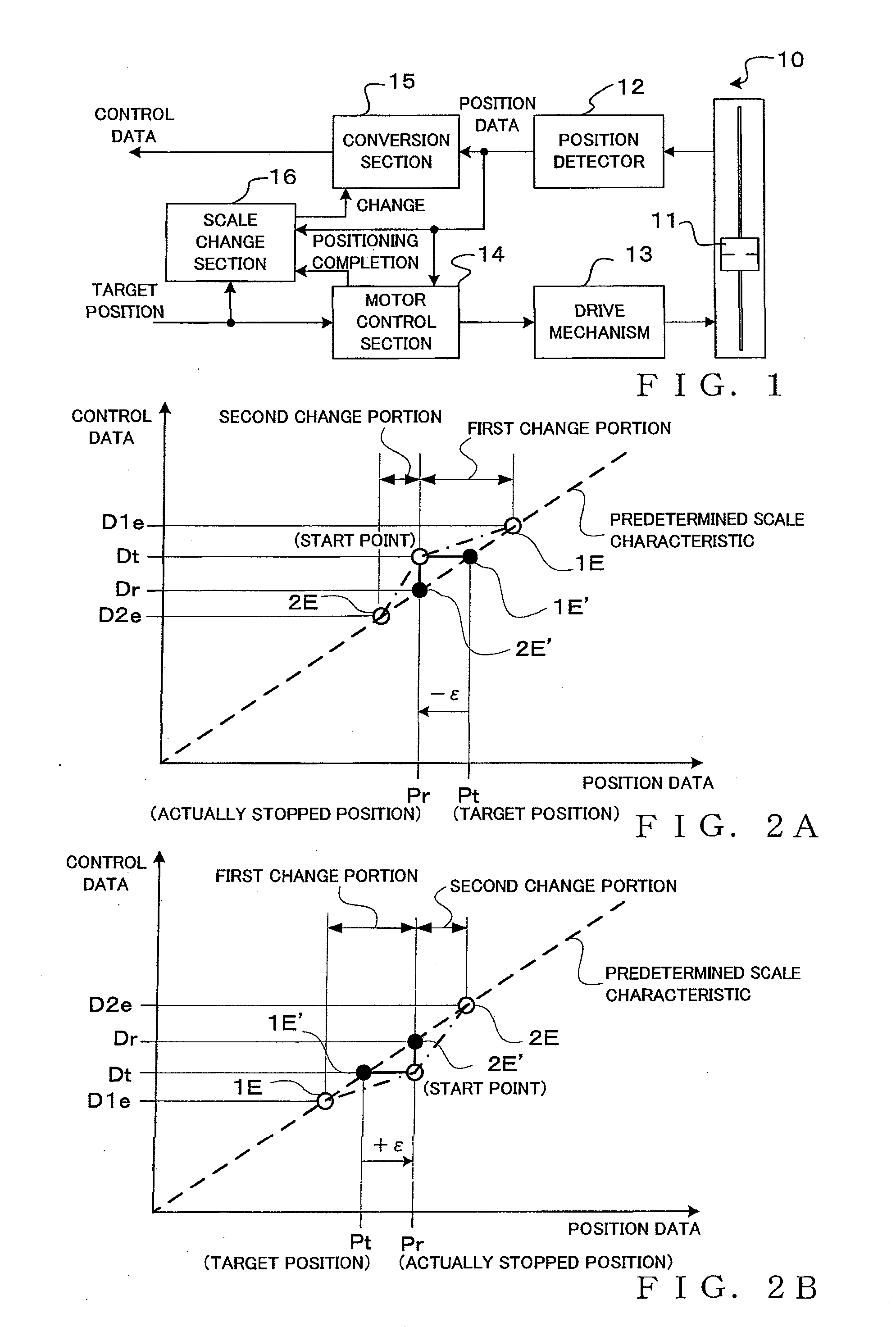
[0010]Preferably, in the change scale characteristic, a second change portion is also established, on an opposite side from the first change portion with respect the position of the start point, so as to extend from the position of the start point in an opposite direction from the first section. During application of the change scale characteristic, the scale change control section changes the control data in such a manner that the value of the control data outputted by the conversion section in correspondence with the position data in the second change portion gradually varies, in accordance with a second change scale, from the value of the control data corresponding to the start point to a value of the control data of the predetermined scale characteristic corresponding to an end point of the second change portion. The application of the change scale characteristic is canceled once the operating position of the operation member reaches the end point of the second change portion. Thus, even where the operation member having previously been stopped at a position deviated from the target position is moved in an opposite direction from the target position, it is possible to achieve a smooth shift from the change scale characteristic to the predetermined scale characteristic. In this case, because the operation member is moved in the opposite direction from the target position, the control data, having at the start point a value corresponding to the target position, never runs counter to a human operator's intention, and thus, there occurs no problem of control data running counter to a human operator's intention even where the second change portion is not set. However, in order to achieve a smooth shift from the change scale characteristic to the predetermined scale characteristic, it is more advantageous to substantively set the second change section.

Problems solved by technology

In the case where the position detecting precision of the position sensor is finer or higher than that of the automatic positioning mechanism, the following problems would arise.
In this case, predetermined control, such as level adjustment, would be undesirably performed on an audio signal on the basis of such position detection data in a slightly inaccurate manner.
Thus, the aforementioned prior art technique can not drastically solve the error problem arising from the inherent positioning precision of the automatic positioning mechanism.
However, if the position detecting precision of the position sensor is so set, an operating position of the operation member can be detected only with a coarse or low resolution even though the position sensor of a high resolution is employed, which presents the problem that effective and efficient utilization of the resource can not be achieved.

Method used


Image

  • Control Data Generation Device and Method
  • Control Data Generation Device and Method
  • Control Data Generation Device and Method

Examples


Embodiment Construction

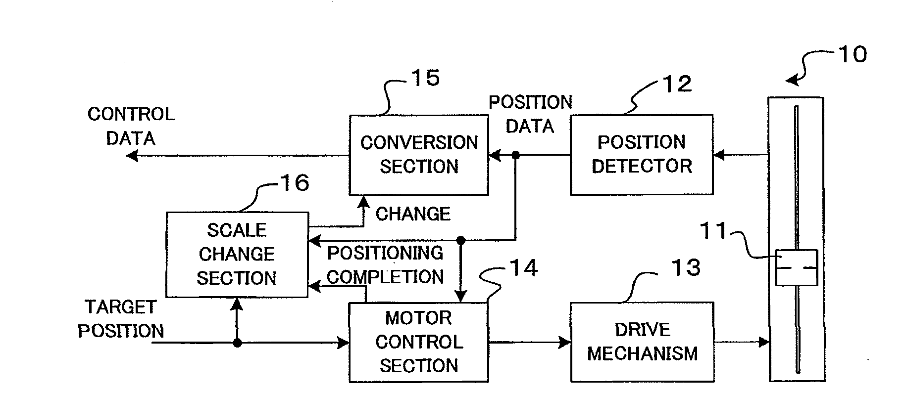
[0026]FIG. 1 is a block diagram showing a general setup of an electric fader 10 that is an embodiment of a control data generation device of the present invention. The electric fader 10 includes a sliding knob (i.e., operation member) 11 operable over a predetermined linear movement range, and the sliding knob 11 is capable of both manual operation and automatic operation. Position detector 12 detects a current operating position of the sliding knob 11 in the predetermined linear movement range and outputs position data, corresponding to the detected current operating position, in a digital value. The position detector 12 may be of any conventionally-known type, such as one comprising a combination of a variable resistor and an analog / digital converter, a magnetic linear encoder, an optical linear encoder or a linear resolver. Drive mechanism 13 includes an electric motor for automatically moving the sliding knob 11 and a mechanism for transmitting the driving force of the motor to ...


PUM


Abstract

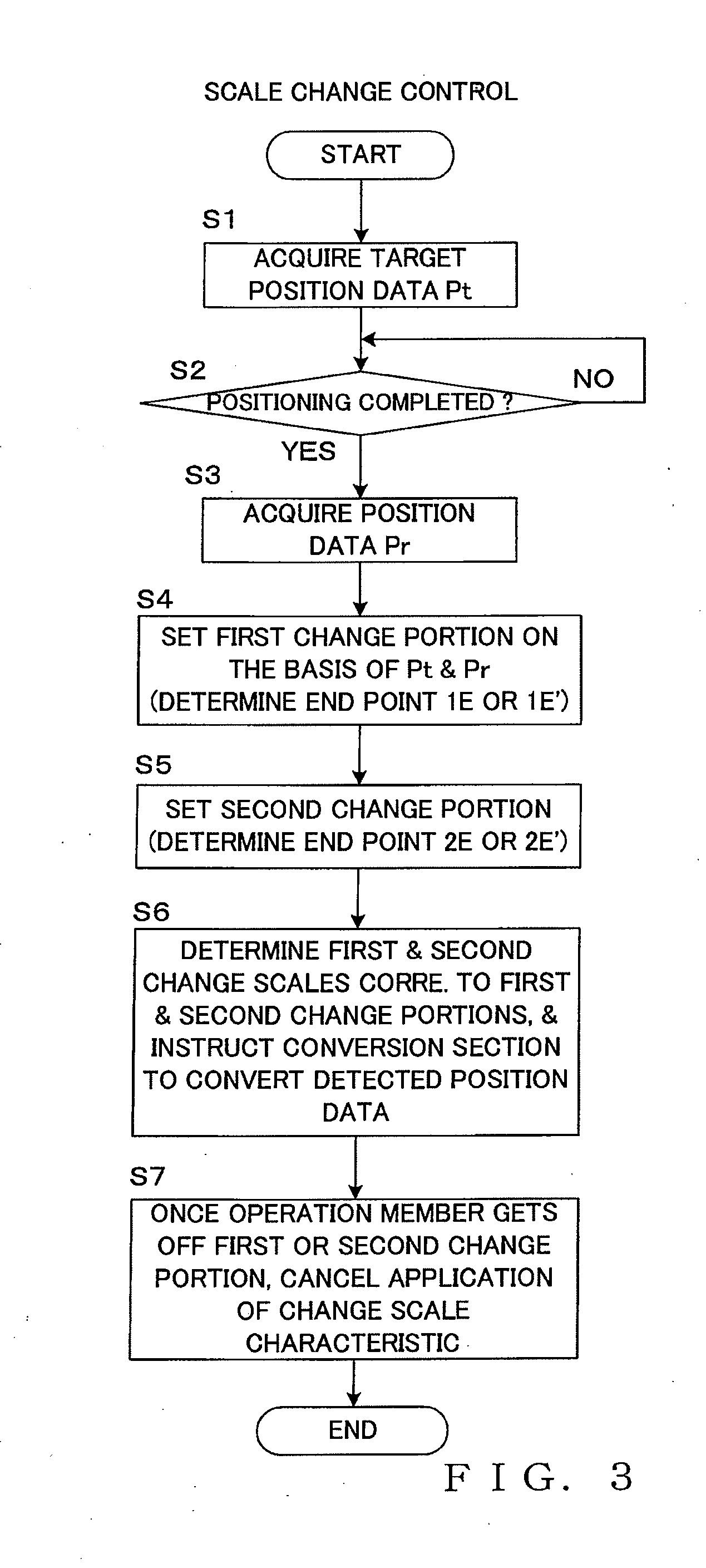
Control data is generated in response to generation, from a position detector, of position data in accordance with a predetermined scale characteristic. Change scale characteristic is applied in manual operation performed immediately after an operation member has been automatically positioned to a target position. In the change scale characteristic, a start point is established such that control data, corresponding to the target position, of the predetermined scale characteristic is outputted in correspondence with the position data outputted at the time of completion of the positioning, but also a first change portion, including a portion extending from a position of the start point at least up to the target position, is established, so that the control data outputted in correspondence with the position data output gradually varies from data corresponding to the start point to data of the predetermined scale characteristic corresponding to an end point of the first change portion.

Description

BACKGROUND[0001]The present invention relates to control data generation devices which detect an operating position of an operation member, employed in an audio mixer apparatus or control equipment and capable of both manual operation and automatic operation, to generate control data corresponding to the detected operating position, and more particularly to a control data generation device which can generate control data, causing no odd feeling, by effectively eliminating a positioning error, produced at the time of automatic operation of an operation member, in response to manual operation of the operation member performed immediately after the automatic operation.[0002]In audio mixer apparatus, there are provided faders (sliding-type operation members) manually operable by a human operator for adjusting / setting levels, frequency characteristics, etc. of audio signals to be mixed or audio signals to be output. Among various types of faders is one constructed as an electric fader ca...

Claims


Application Information

Patent Timeline
IPC IPC(8): H04B1/00
CPCH04H60/04G11B27/038G11B27/34G11B27/031G06F3/0362
Inventor AISO, MASARU
Owner YAMAHA CORP
Learn More