Cutting insert for high-efficient cutting

a cutting insert and high-efficiency technology, applied in the direction of cutting inserts, shaping cutters, manufacturing tools, etc., can solve the problems of cutting inserts being damaged, cutting edges being limited, cutting edges being used, etc., to achieve high-efficiency cutting, increase stiffness, and stably conduct cutting processes

Active Publication Date: 2010-02-11
KORLOY
View PDF11 Cites 64 Cited by
  • Summary
  • Abstract
  • Description
  • Claims
  • Application Information

AI Technical Summary

Benefits of technology

[0010]Accordingly, the present invention has been made keeping in mind the above problems occurring in the prior art, and an object of the present invention is to provide a cutting insert for high-efficiency cutting which has increased stiffness and thus makes it possible to stably conduct a cutting process despite the realization ...

Problems solved by technology

However, in the case of a conventional single-sided cutting insert, which is typically used in milling, the number of cutting edges to be used is limited due to the single-sided structure.
Furthermore, the conventional single-sided cutti...

Method used


Image

  • Cutting insert for high-efficient cutting
  • Cutting insert for high-efficient cutting
  • Cutting insert for high-efficient cutting

Examples


Embodiment Construction

[0034]The above and other objects, features and advantages of the present invention will be more clearly understood from the following detailed description.

[0035]Hereinafter, a preferred embodiment of the present invention will be described with reference to the attached drawings.

[0036]Reference now should be made to the drawings, in which the same reference numerals are used throughout the different drawings to designate the same or similar components. Furthermore, in the description of the present invention, a detailed explanation of well-known techniques and constructions will be omitted in order to more clearly describe the gist of the present invention.

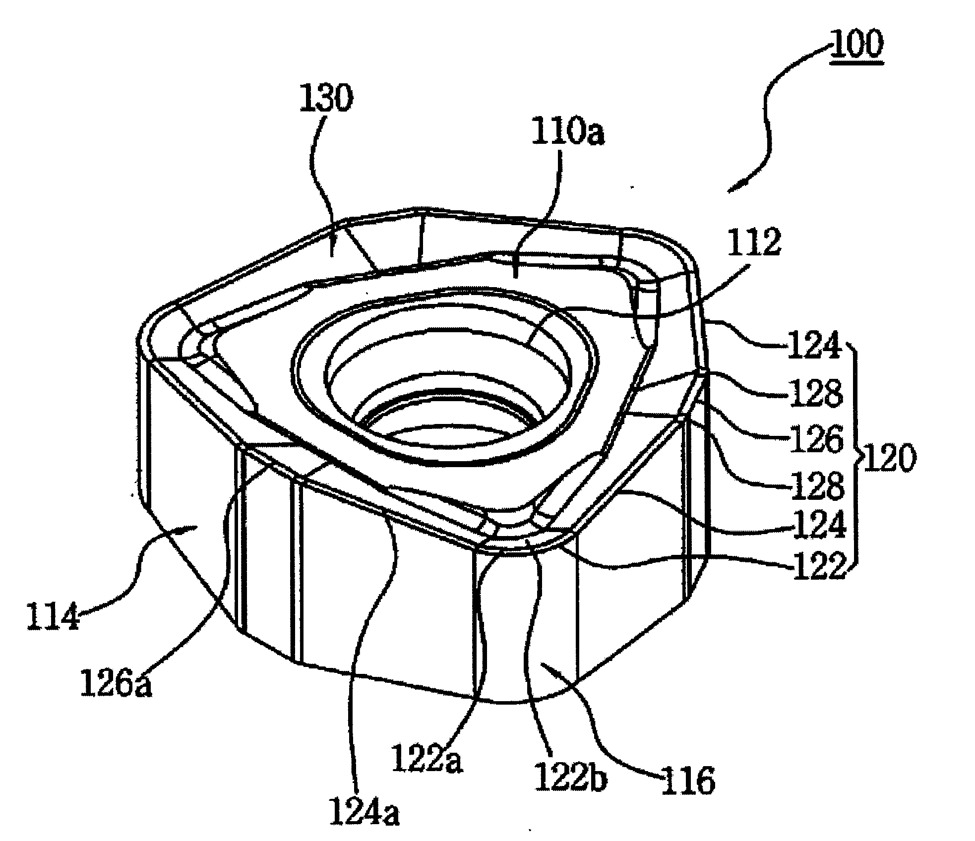
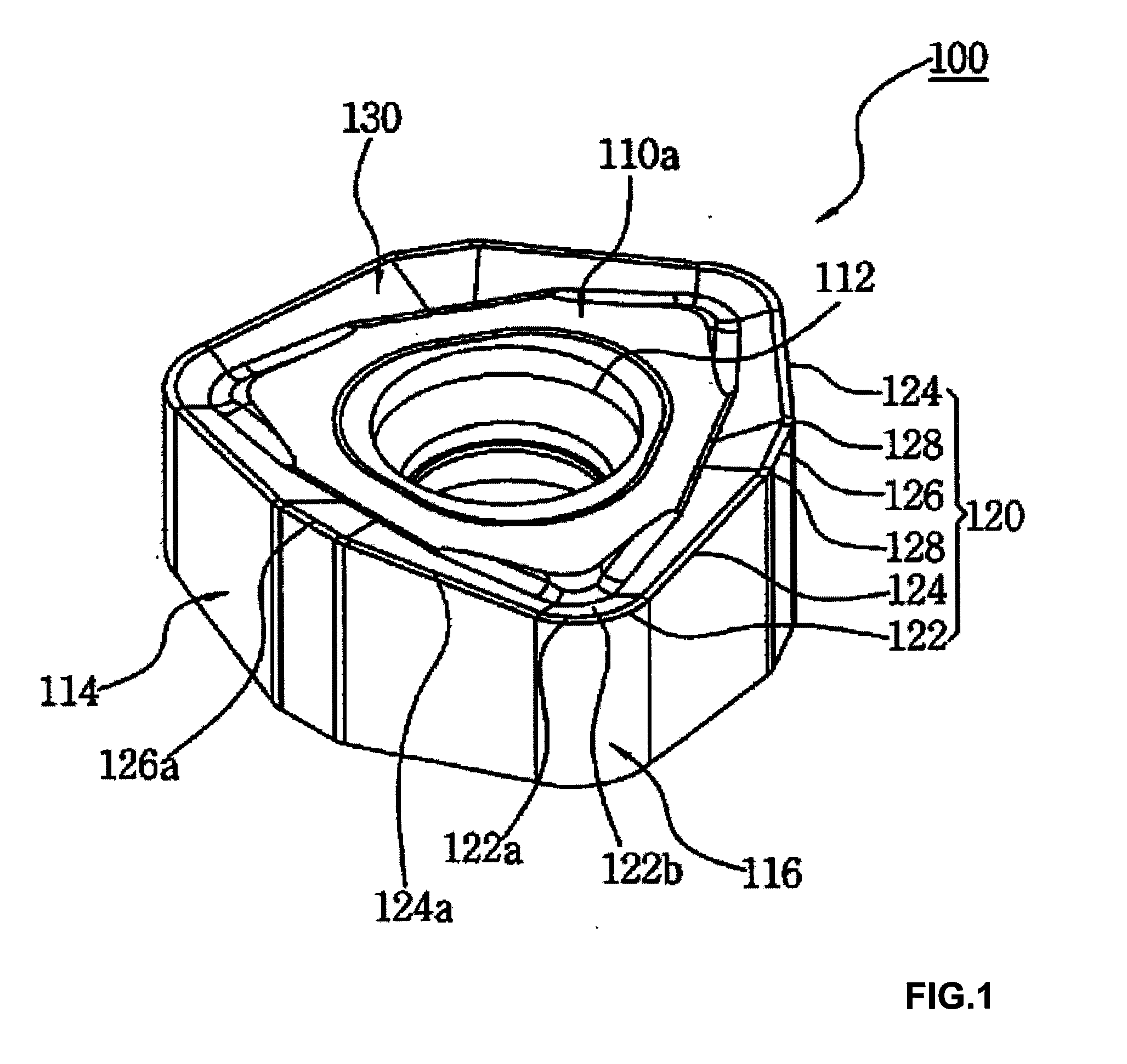
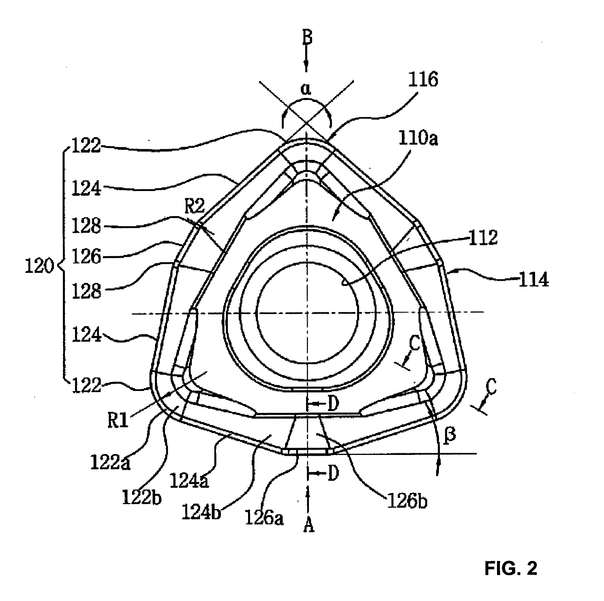
[0037]FIG. 1 is a perspective view of a cutting insert for high-efficiency cutting, according to the present invention. FIG. 2 is a plan view of the cutting insert of FIG. 1. FIG. 3 is a view showing the cutting insert from the direction indicated by the character “A” of FIG. 2. FIG. 4 is a view showing the cutting insert from th...


PUM

PropertyMeasurementUnit
Angleaaaaaaaaaa
Angleaaaaaaaaaa
Angleaaaaaaaaaa

Abstract

A cutting insert for high-efficiency cutting is disclosed. The cutting insert includes an upper surface (110a), a lower surface (HOb), side surfaces (114) and corner side surfaces (116), which connect the side surfaces to each other. A circular opening is formed through the central portions of the upper and lower surfaces. In the cutting insert, cutting edges are formed by respective junctions between one of the upper and lower surfaces and the side surfaces and between one of the upper and lower surfaces and the corner side surfaces. The cutting edges comprise three corner cutting edges (122), six major cutting edges (124), which extend from opposite ends of the corner cutting edges towards the neighbor corner cutting edges, and three minor cutting edges (126), which are connected between the major cutting edges. Furthermore, the cutting edges may be formed on both the upper surface and the lower surface.

Description

BACKGROUND OF THE INVENTION[0001]1. Field of the Invention[0002]The present invention relates, in general, to cutting inserts for high-efficiency cutting and, more particularly, to a cutting insert for high-efficiency cutting which has increased stiffness and thus makes it possible to stably conduct a cutting process despite the realization of rapid feed cutting, in which the number of cutting edges is increased, thus extending the lifetime of the cutting insert, and which can be applied to a milling operation and a turning operation, thus realizing a multi-functional structure and being economical, and can increase productivity when cutting and realize high-quality cutting.[0003]2. Description of the Related Arts[0004]Generally, cutting tools are used to cut iron, nonferrous workpieces, and nonmetallic workpieces. Typically, cutting tools are held by machines and cut workpieces to form them into desired shapes. Such a cutting tool includes a cutting insert, which has a cutting edge...

Claims


Application Information

Patent Timeline
IPC IPC(8): B23C5/02
CPCB23B27/141B23B2200/0495B23B2200/087Y10T407/23B23C5/06B23C5/202B23B2200/286B23C5/02B23C5/20
Inventor SUNG, WOOK JUNGSUNG, IN SIK
Owner KORLOY
Why Eureka
Try Eureka