
Method of controlling motor-driven washing machine and control system for the same

a technology of motor-driven washing machines and control systems, which is applied in the direction of motor/generator/converter stoppers, dynamo-electric converter control, detergent compounding agent control, etc., can solve the problems of motor-clutch mechanism noise, user serious harm, and many problems, so as to reduce the speed of the motor, avoid any motor damage, and minimize the effect of tim

Inactive Publication Date: 2010-02-18
LG ELECTRONICS INC
View PDF29 Cites 1 Cited by
  • Summary
  • Abstract
  • Description
  • Claims
  • Application Information

AI Technical Summary

Benefits of technology

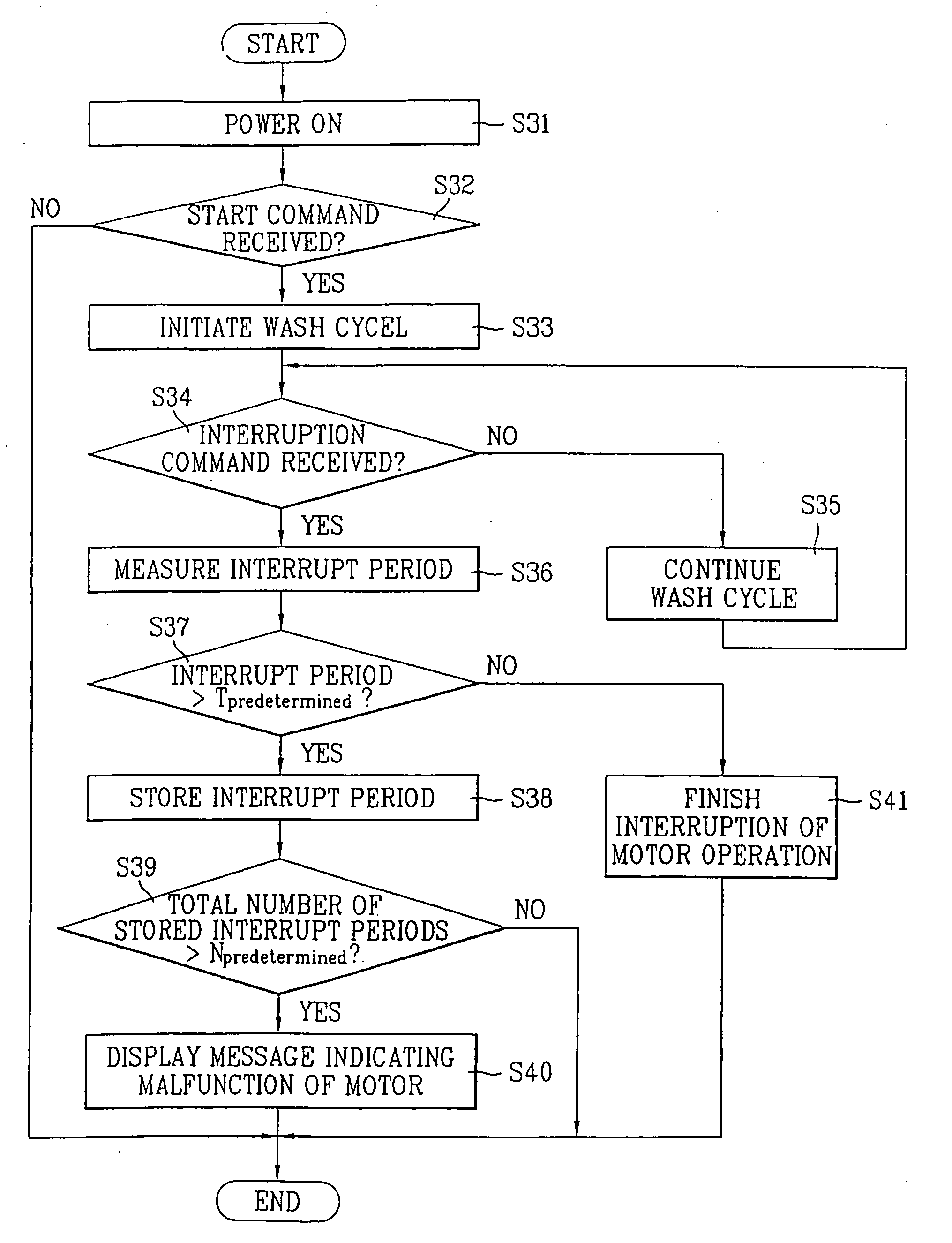
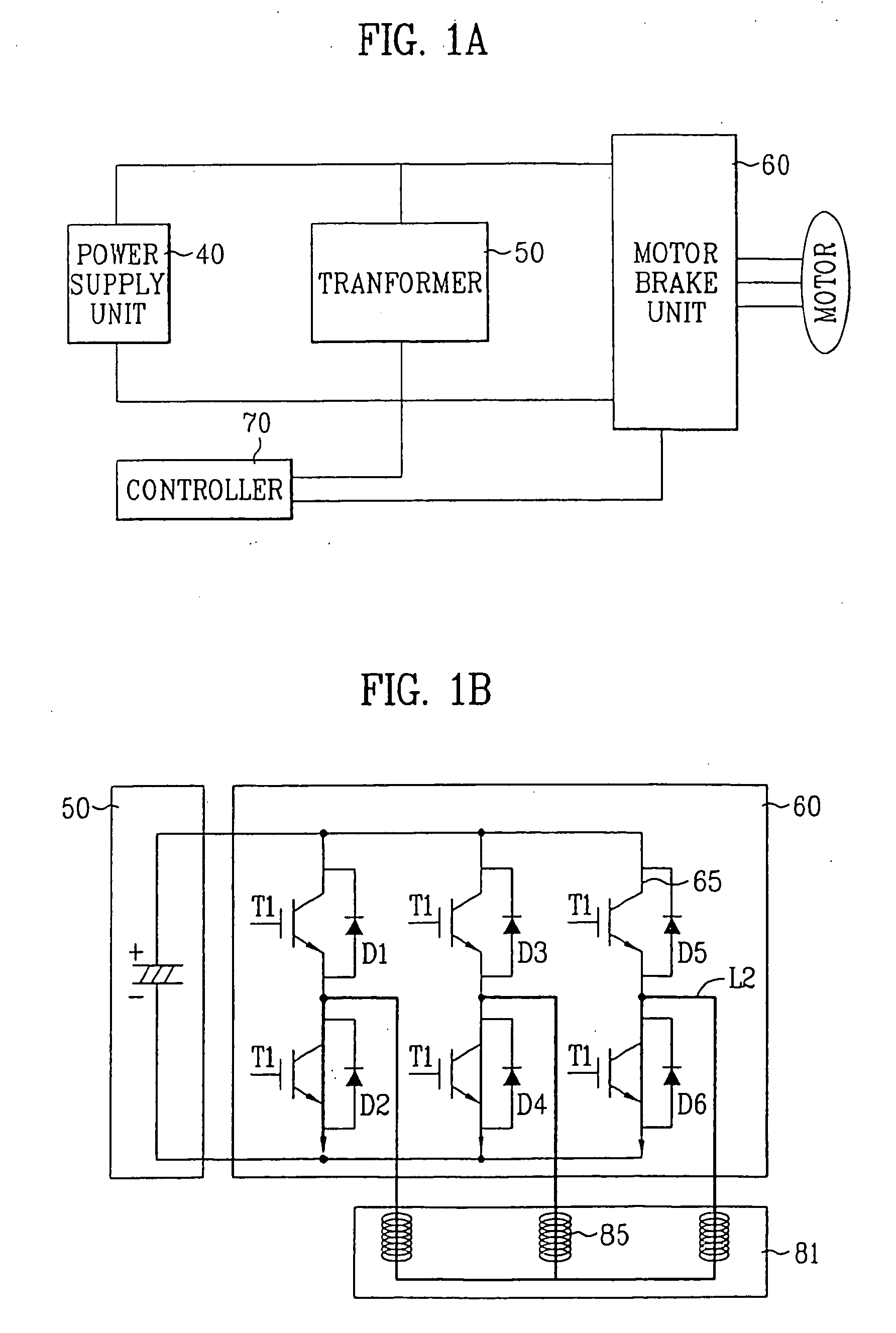
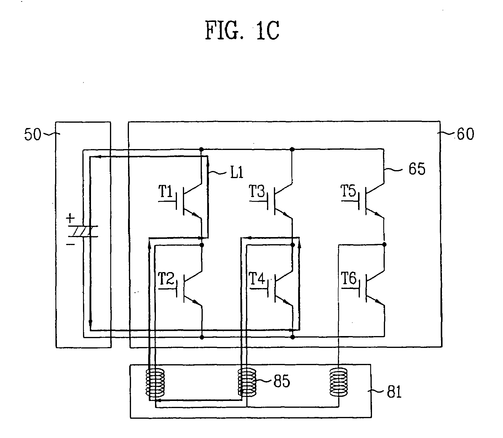
The present invention provides a method and control system for a motor-driven washing machine that can prevent motor-clutch mechanism from generating noise and being damaged, even if the initial algorithm for braking the motor is not executed properly. The method also allows for proper control even if the motor-braking resistor is malfunctioning. The control system can detect and prevent malfunctions of the motor, and the method and control system can minimize the time it takes to reduce the motor speed. The invention also provides a circuit for limiting a motor current in an electrical appliance. Overall, the invention improves the performance and reliability of motor-driven washing machines.

Problems solved by technology

Because the wash tub rotates at a very high speed, many problems can occur.
For example, if the operation of the motor is not stopped properly when a user mistakenly opens a washer door and sticks a hand into inside of the tub, the user may be seriously harmed.
In another example, when a control for braking a motor in motion during a spin cycle is not properly done, the motor-clutch mechanism may generates a noise and the mechanism can be damaged due to the motion of the heavy wash tub at a high speed.

Method used


Image

  • Method of controlling motor-driven washing machine and control system for the same
  • Method of controlling motor-driven washing machine and control system for the same
  • Method of controlling motor-driven washing machine and control system for the same

Examples


embodiment (

10)

[0112]FIG. 10 illustrates a circuitry for limiting a motor current in an electrical appliance according to a tenth embodiment of the present invention. Referring to FIG. 10, the current limiting circuitry includes a microprocessor 999, a power source Vcc supplying a source voltage of 5V, a first resistor R1 having a resistance of 33 k and a dip switch 997 connected between the power source Vcc and a ground in series, a capacitor C1 connected to the dip switch 997 in parallel, an op amp 998 having an inverting input connected to a node between R1 and the dip switch 997 and an output connected to the microprocessor 999, and a third resistor R3 having a resistance of 0.027 k, which is connected between the noninverting input of the op amp 998 and a ground.

[0113]Reference will now be made in detail to the operation of the current limiting circuitry shown in FIG. 10. The dip switch 997 comprises a plurality of resistors having different resistances (e.g., 1.3 k, 1.5 k, 1.8 k, 2.0 k, a...


PUM


Abstract

A control system for a motor-driven washing machine. The control system includes an electrical motor; a driving unit that applies an input voltage to the motor to drive the motor; a voltmeter that measures a reverse voltage generated by the motor for each predetermined period; and a microprocessor reducing a speed of the motor if the measured reverse voltage is less than or equal to a predetermined voltage level.

Description

CROSS-REFERENCE TO RELATED APPLICATIONS[0001]This application claims the benefit of Korean Application No. P2002-26886 filed on May 15, 2002, Korean Application No. P2002-27127 filed on May 16, 2002, Korean Application No. P2002-27132 filed on May 16, 2002, Korean Application No. P2002-40211 filed on Jul. 11, 2002, Korean Application No. P2002-40292 filed on Jul. 11, 2002, Korean Application No. P2002-44687 filed on Jul. 29, 2002, Korean Application No. P2002-73580 filed on Nov. 25, 2002, Korean Application No. P2002-73898 filed on Nov. 26, 2002, Korean Application No. P2002-74052 filed on Nov. 26, 2002, and Korean Application No. P2002-74054 filed on Nov. 26, 2002, all of which are hereby incorporated by reference as if fully set forth herein.BACKGROUND OF THE INVENTION[0002]1. Field of the Invention[0003]The present invention relates to a washing machine, and more particularly, to a method of controlling a motor-driven washing machine and a control system for the same.[0004]2. Dis...

Claims


Application Information

Patent Timeline
Patent Type & Authority Applications(United States)
IPC IPC(8): D06F33/00D06F33/02D06F37/30D06F37/40D06F39/14H02P3/18H02P3/22H02P27/06
CPCD06F37/304D06F2202/065Y02B40/52H02P3/22D06F2204/065Y02B40/00D06F34/08D06F2103/24D06F2105/48D06F33/47
Inventor KOO, BON KWONKONG, KWON KILYU, JAE CHEOLLEE, WOON YONGBANG, JONG CHULOH, MIN JINKWEON, SONJONG, KIM HOCHO, IN HAENG
Owner LG ELECTRONICS INC
Learn More