
Ball Bearing

a retainer and ball bearing technology, applied in the direction of bearings, shafts and bearings, rotary machine parts, etc., can solve the problems of abnormal wear or seizure, large amount of grease, and difficult to leak out the grease that adheres to the inner peripheral surface of the retainer, so as to prevent harmful noise and prevent the leakage of grease inside the ball bearing

Inactive Publication Date: 2006-07-04
NSK LTD
View PDF17 Cites 2 Cited by
  • Summary
  • Abstract
  • Description
  • Claims
  • Application Information

AI Technical Summary

Benefits of technology

This design effectively prevents grease leakage and reduces retainer noise, maintaining adequate lubrication and durability by ensuring the grease flows into the pockets without obstructing the flow, thus reducing friction and wear.

Problems solved by technology

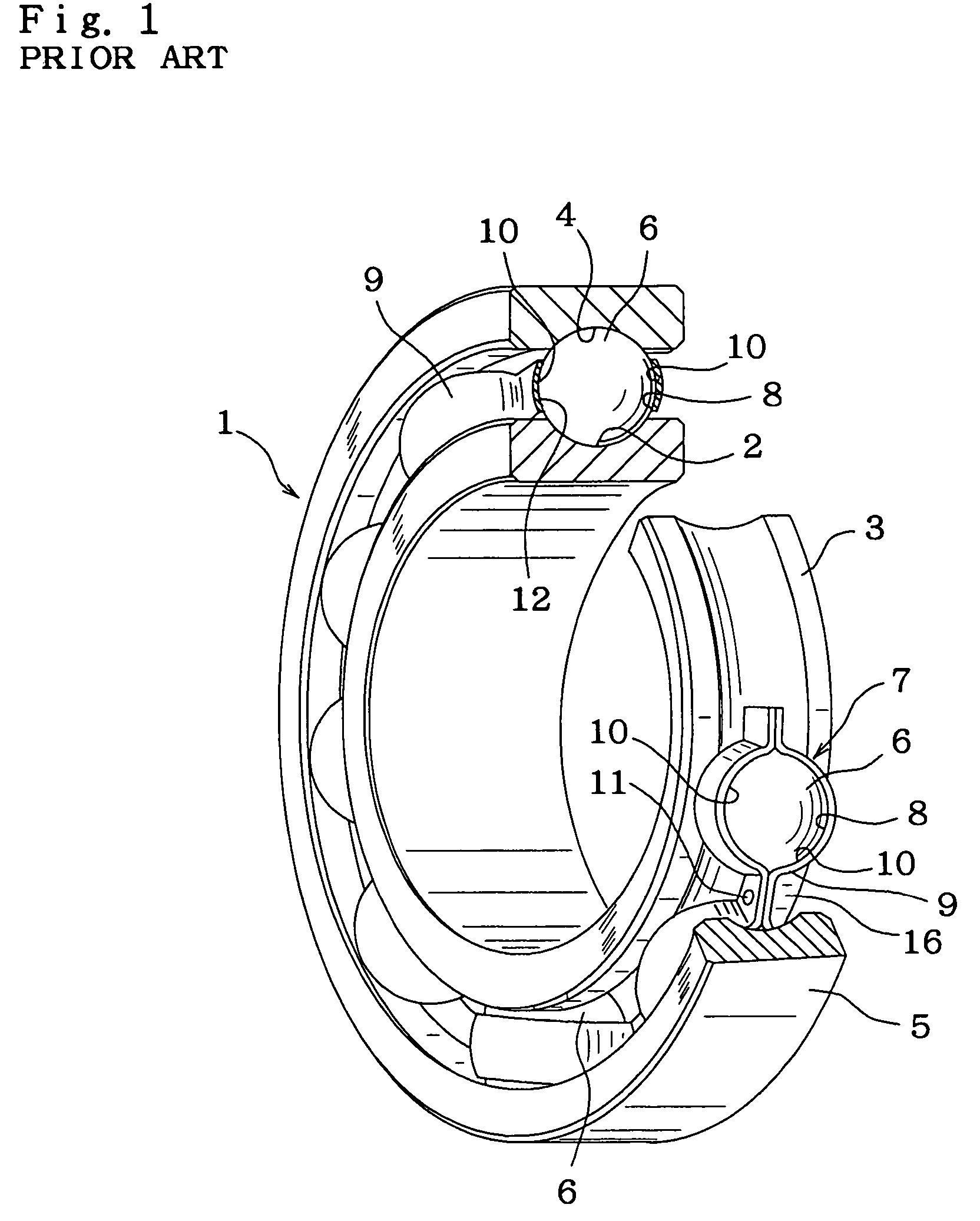
Therefore, over a long period of use, the amount of grease 20 that remains in this space 16 gradually decreases, and there is a possibility that abnormal wear or seizure will occur due to poor lubrication.
With this prior construction, it is difficult for the grease that adheres to the inner peripheral surface of the retainer to leak out.
Particularly, it is necessary to perform finishing such as polishing to the section on both ends of the outer peripheral surface of the inner race that is separated from the inner-race track, which was not necessary originally, so that the manufacturing cost increases.
Also, the size of the ball bearing to which this can be applied is limited, and it is difficult to apply the construction to a small-diameter ball bearing, or to a ball bearing that is thin in the axial direction.
Moreover, in the case of the construction disclosed in Publication of Jitsu Kai Hei 7-10556, a separate part or slinger is required just in order to direct the grease to the outside, so that the number of parts increases as well as the number of assembly steps, thus increasing the manufacturing cost.
Also, as in the case of the construction disclosed in Publication of Toku Kai Hei 8-270662, the size of the ball bearing to which it can be applied is limited, and it is difficult to apply the construction to a small-diameter ball bearing, or to a ball bearing that is thin in the axial direction.
Furthermore, in the case of the construction of forming a plurality of sliding contact sections, or of forming a multi-staged labyrinth seal, not only does the rotation torque of the ball bearing increase and the heat generated during high-speed operation become severe, but in many cases it is not possible to sufficiently obtain the effect of leak prevention.
Moreover, as the pressure inside the space 16 where the rolling elements 6 are located rises due to rolling friction or grease mixing resistance during use, this elastic deformation of the seal lip 111 becomes even greater, and thus grease leakage is even more severe.
In addition, it becomes easy for surface contact to occur between the end edge 112 of the seal lip 111 and the sliding contact area of the seal groove 113 to occur, making it difficult to maintain stable contact.
Therefore, when this construction is used in cases where the outer race 5 rotates, it particularly becomes difficult to prevent foreign matter from getting inside.
Also, in the case of the construction shown in FIG. 10, it becomes easy for a contact state in the sliding contact section between the outer peripheral surface on the end of the inner race 3 and the edge of the seal lip 111 to be varied due to offset of the center axis of the inner race 3 and outer race 5 that occurs due to external force that is applied during use because of shape and dimensional errors of the seal groove 113, and thus it becomes difficult to obtain stable seal performance.
Moreover, in the case of the construction disclosed in Japanese Patent Publications Toku Kai Hei 7-293571 and Toku Kai Hei 7-139553, the seal lip comes in sliding contact with the axial outer one of the wall surfaces, so it is necessary to form an air hole for releasing pressure in the internal space, and thus it becomes easy for grease to leak from this air hole.
Furthermore, in the case of the construction disclosed in Japanese Patent Publication Jitsu Kou Hei 6-27859, it becomes easy for the seal lip for the labyrinth clearance to become hard due to heat degradation, and thus it becomes impossible to adequately maintain the flexibility of the grease lip for a long period of time, and it is difficult to maintain good seal characteristics over a long period of time.
When this kind of grease leakage occurs, the amount of grease that remains in the space 16 gradually decreases over a long period of time, and there is a possibility that abnormal wear or seizure could occur due to poor lubrication.
The grease that has once entered inside the retainer remains on the outer peripheral surface of the still inner race 3 and it becomes difficult for it to return to the outside.
In this case, the grease does not flow smoothly enough to the radially outside, and there is a possibility that grease radially inside the retainer 7 will build up.
In that case, there is a further possibility that grease leakage will not be sufficiently prevented.
When part of the grease enters inside the seal groove 113 in this way, it is not possible to adequately prevent grease leakage.

Method used


Image

  • Ball Bearing
  • Ball Bearing
  • Ball Bearing

Examples


eleventh embodiment

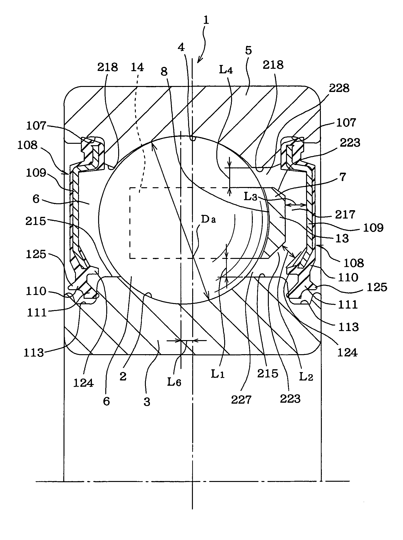
[0150]Next, a twelfth example of the embodiment of the invention is shown in FIGS. 39 and 40. In this example, a dust seal lip 125 is formed on the outside of the seal lip 111 on the inner peripheral edge of the elastic member 110 of the seal plate 108 to protrude in the axial direction from the inner peripheral section on the outer surface of the seal lip 111 such that it covers the outside of the outer half of the opening of the seal groove 113. Except that the shape of the dust lip 125 is different and that the shape of the seal lip 111 is a little different to match it, the construction and functions of this embodiment are nearly the same as those of the eleventh embodiment described above.

[0151]A experimental test performed by the inventors to confirm the effect of the invention is explained below. In this test, the following examples were used under identical conditions, and the rate of grease leakage and the amount of water seepage were measured for comparison;

[0152]a convent...

example i

[0154 of the rolling bearing of this invention with the seal plate 108 shown in FIGS. 37 to 38 installed therein, and

example ii

[0155 of the rolling bearing of this invention with the seal plate 108 shown in FIGS. 39 and 40 installed therein.

[0156]The dimensions of the conventional example, Comparative Example I, Example I and Example II are shown in Table 1, and the measurement results for the grease leakage rate are shown in FIG. 41, and the measurement results for the water seepage are shown in FIG. 42.

[0157]The test was performed on eight samples of like example for measuring the grease leakage rate, for a total of 32 samples, and on four samples of like example for measuring the amount of water seepage, for a total of 16 samples.

[0158]

TABLE 1ConventionalComparativeExampleExampleExampleExample IIIIInterference L0.26 mm0.08 mm0.13 mm0.13 mmRate of3.3%1.0%1.6%1.6%InterferenceL toBallDiameterduring halt2.3 N / mm10.4 N / mm4.6 N / mm4.4 N / mmP / L(230 gf / mm)(1060 gf / mm)(470 gf / mm)(450gf / mm)during-2.6 N / mm11.4 N / mm5.0 N / mm4.9 N / mmoperation(270 gf / mm)(1160 gf / mm)(510 gf / mm)(500gf / mm)αabout 9.5°about 40°about 36°about ...


PUM


Abstract

A retainer for a ball bearing formed in a generally annular shape and having a plurality of pockets arranged in a circumferential direction, respectively, to rollably hold a plurality of balls along a pitch circle, respectively, the pockets each having an inner peripheral surface comprising a radially inner section which is located inward of the pitch circle of the balls in the radial direction of the retainer, and has an inner diameter larger than the diameter of the balls, such that the gap between the radially inner section of the inner peripheral surface of the pockets and the rolling surface of the balls gradually increases toward the opening of the pockets on the inner side in the radial direction of the retainer, and that the maximum inscribing circle of the opening of the pockets on the outer side in the radial direction of the retainer has a diameter smaller than the diameter of the balls.

Description

CROSS REFERENCE TO RELATED APPLICATIONS[0001]This is a division of U.S. patent application Ser. No. 09 / 691,457, filed Oct. 18, 2000 now U.S. Pat. No. 6,719,459.TECHNICAL FIELD OF THE INVENTION[0002]This invention relate to a ball-bearing retainer (also referred to as cage) and ball bearing, particularly to an improvement of ball bearings used in various rotating mechanical devices and the retainers used in those ball bearings, and more particularly to providing inexpensively a structure to prevent lubrication grease enclosed inside the ball-bearing from leaking out, while at the same time makes it possible to suppress the generation of harmful noise called retainer noise.BACKGROUND ON THE INVENTION[0003]Ball bearings, such as the ball bearing 1 shown in FIG. 1, are widely used for supporting various rotating parts, such as the bearings of various rotating mechanical devices. This ball bearing 1 comprises an inner race 3, that has a inner-race track (also referred to as raceway) 2 fo...

Claims


Application Information

Patent Timeline
Patent Type & Authority Patents(United States)
IPC IPC(8): F16C33/76F16C33/38F16C33/78
CPCF16C33/416F16C33/7823F16C33/418F16C33/7856F16C2240/40F16C2240/30F16C2240/12F16C2240/34F16C19/06
Inventor GOTOH, FUSASUKE
Owner NSK LTD
Learn More