Expandable tubulars for use in geologic structures

a technology of expandable pipes and geologic structures, which is applied in the direction of drilling pipes, drilling casings, borehole/well accessories, etc., can solve the problems of high cost, slow drilling and construction of oil and gas wells, and high cost of some wells

Inactive Publication Date: 2010-02-18
DTS TECH
View PDF16 Cites 109 Cited by
  • Summary
  • Abstract
  • Description
  • Claims
  • Application Information

AI Technical Summary

Benefits of technology

[0013]Some of the leaves are secured to each other by welding, soldering, brazing, mechanical fasteners, surface features, adhesives and any other coupling mechanisms. The attachment points can be one edge of a leaf to a more central section of an adjacent leaf. In order to allow for radial expansion and contraction, some of the leaves surfaces or edges are not coupled to an adjacent leaf. The uncoupled leaves allow some of the adjacent leaves to slide against each other which facilitates the diameter of the inventive tubular to expand or contract. In the preferred embodiment, the leaves are made of steel with good elasticity characteristics. During compression, the diameter decreases and the leaves are bent elastically inward. The tubular is held in the compressed state with energy stored in each of the leaves. When the tubular is deployed, the restraints are released and the elastic leaf material will recover to their original shape or expand against the inner diameter of the borehole.
[0017]In another embodiment, the leaves have ratchet mechanisms that use tabs to engage slots and teeth formed in adjacent leaves. The tabs may include elongated arm pieces that are attached to the leaf but bent out of the planes of the leaf. The tabs engage slots in the adjacent leaves that may be similar in size so that the tab can slide within the leaf The tab and slot may have teeth that are angled so that they allow ratcheted movement in only an expansion direction. The ratchet mechanism can be configured so that the teeth of the tab and slot only engage after the casing has been expanded to a minimum expansion diameter. Because the tabs and slots couple the leaves of the casing, they effectively integrate the entire thickness of the casing into a unitary assembly.

Problems solved by technology

Despite a century of technological advances, drilling and construction of oil and gas wells remains a slow, dangerous, and expensive process.
The costs of some wells can exceed 100 million dollars.
A significant contributor to these high costs is due to suspension of drilling in order to repair geologically-related problem sections in wells.
These problems can include, but are not limited to, lost-circulation, borehole instability, and well-pressure control.
However, these problems are still generally rectified only by costly and time-consuming casing and cementing operations.
As is well known in the art, disadvantages of telescoping practices are numerous.
These disadvantages include, but are not limited to, excess excavation work, special equipment for over-size rock borings, and production of costly waste products.
Despite major expenditures and efforts, drilling might not reach the targeted resources.
If the final telescope casing size (or production string) is too small to economically produce the hydrocarbon resource, the result is a failed well.
The expanded casing assembly must, however, meet certain strength requirements and allow passage of subsequent 9⅝ inch outer diameter casing strings as drilling deepens and new problem zones are encountered.
The foregoing deforming process inherently requires use of relatively soft steels, which may not provide the desired mechanical properties required in the environments of oil and gas wells.
It is believed that most potential users cannot utilize current expandables due to fundamentally unsolvable technical or economic issues.
For example, it is believed that conventional expandable tubulars do not provide a good seal, because they do not comply adequately with the irregular wall surfaces of wells.
As a result, it is believed that conventional expandable tubulars can never properly comply or seal.
However, it is also well known that high-levels of deformity can cause stress-cracking, a variety of metallurgical problems, and decreased mechanical properties.
A further disadvantage of presently known expandable tubulars is that as the tubular is deformed radially, such outward radial expansion causes the overall length of the tubular to be shortened by some 1% to 3% or more.
Such shrinkage along the longitudinal axis of the tubular member is undesirable.
An inability to supply extra material to the shrinkage can impede radial expansion.
For example, if the pre-expanded casing becomes “stuck” or otherwise placed into tension longitudinally, the need to service the shrinkage cannot be met and the deforming material becomes prematurely strained.
This is also a major source of difficulty when expanding threaded connections.

Method used


Image

  • Expandable tubulars for use in geologic structures
  • Expandable tubulars for use in geologic structures
  • Expandable tubulars for use in geologic structures

Examples


Embodiment Construction

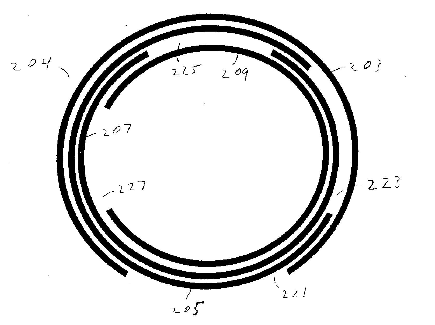
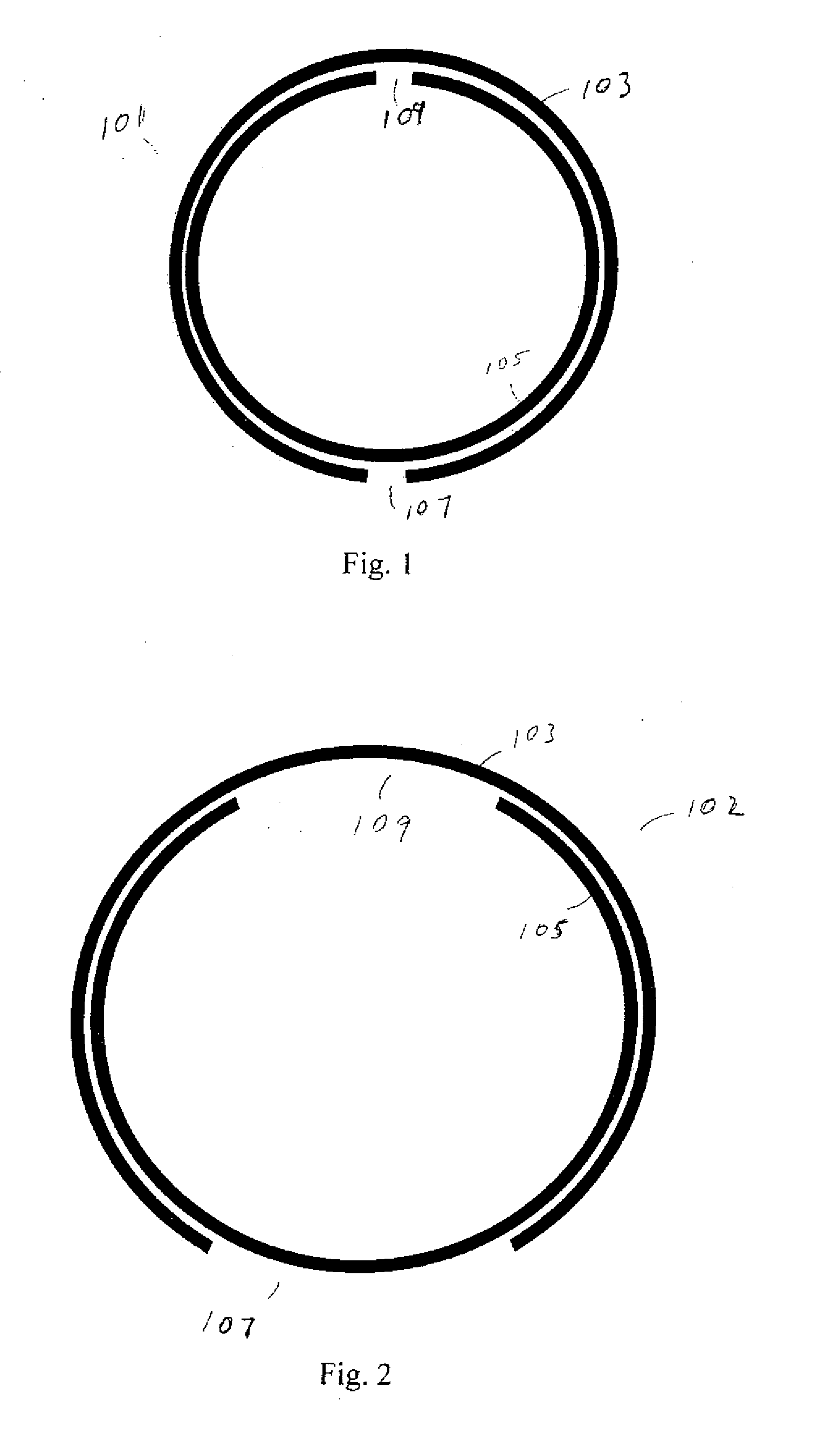
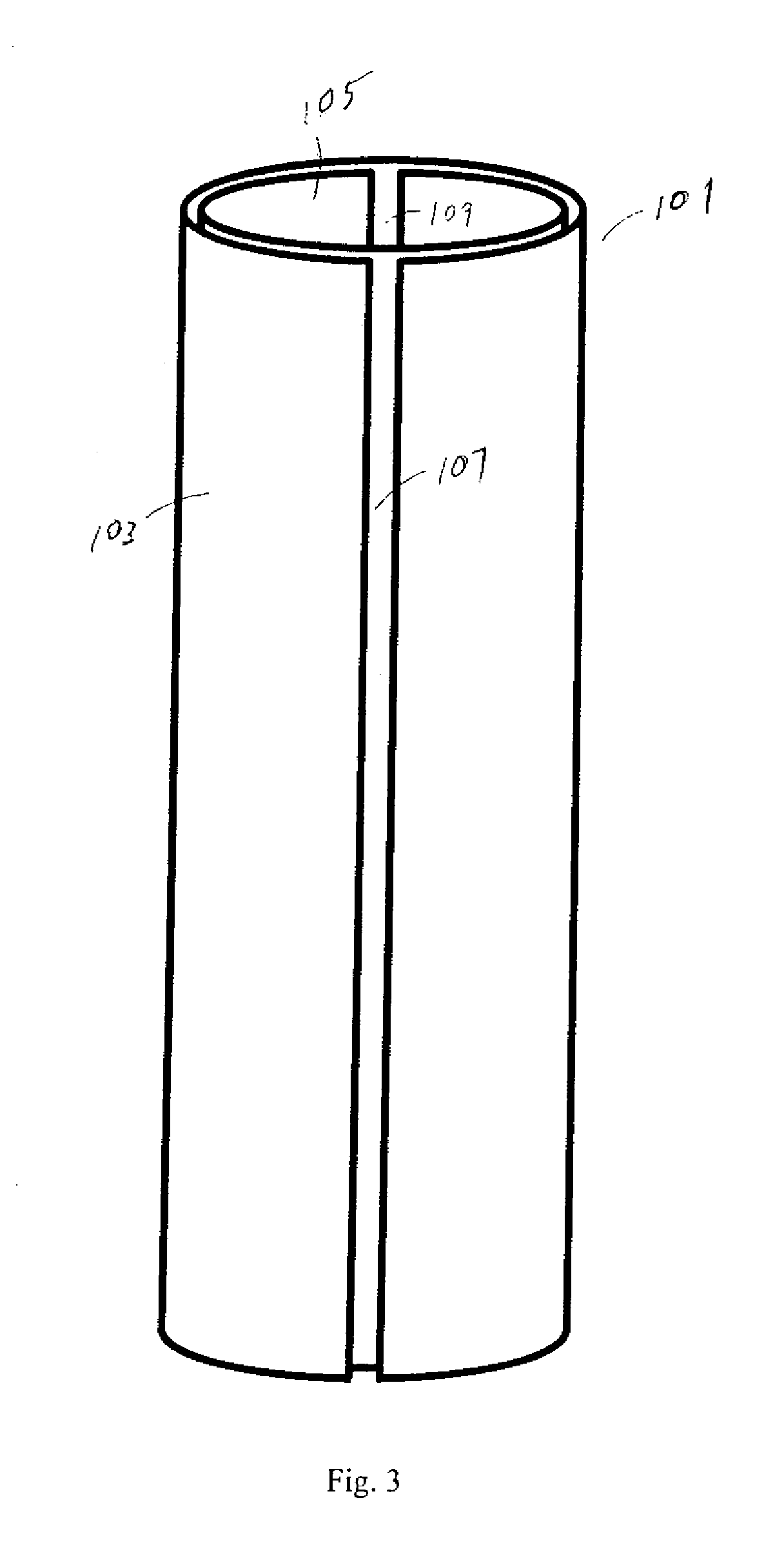
[0052]The present invention is directed towards tubular structures that are expandable in diameter. The inventive tubular structures may be compressed and placed into a borehole in the ground or any other structure. In the compressed state, the tubular is able to fit within the inner diameter of a deployed tubular and provide a suitable circulating annulus. Thus, the compressed tubular is placed into a borehole through other deployed tubulars. Once the tubular structure is properly positioned, which may or may not include attachments to adjacent deployed tubulars, it is expanded in diameter until its outer diameter is resisted by the rock borehole. The expanded casing may penetrate the walls of the borehole.

[0053]In an embodiment, the inventive expandable tubular may comprise a plurality of expandable springs that are sheets of strong elastic material that are formed into a generally cylindrical shape from at least one sheet of material and have at least two free ends that extend al...


PUM


Abstract

An expandable tubular includes a plurality of leaves formed from sheet material that have curved surfaces. The leaves extend around a portion or fully around the diameter of the tubular structure. Some of the adjacent leaves of the tubular are coupled together. The tubular is compressed to a smaller diameter so that it can be inserted through previously deployed tubular assemblies. Once the tubular is properly positioned, it is deployed and coupled or not coupled to a previously deployed tubular assembly. The inventive tubular is useful for all types of wells and boreholes.

Description

CROSS-REFERENCE TO RELATED APPLICATIONS[0001]The present invention claims priority to U.S. Patent Application for EXPANDABLE TUBULARS FOR USE IN PRODUCTION OF HYDROCARBONS, application Ser. No. 10 / 925,521 and PCT Patent Application for EXPANDABLE TUBULARS FOR USE IN PRODUCTION OF HYDROCARBONS Application No. PCT / US2004 / 027580, both filed Aug. 25, 2004, U.S. Patent Application for Expandable Split Pipes For Use In Geologic Structures, Application No. 60 / 781,047 filed Mar. 10, 2006, U.S. Patent Application for High Ratio, Elastic Region Tubular Expansion, Application No. 60 / 789,835 filed Apr. 6, 2006, U.S. Patent Application for Split Pipe Casing Application No. 60 / 793,024 filed Apr. 18, 2006, U.S. Patent Application for Expandable Tubulars For Use In Geologic Structures [Coil] Application No. 60 / 808,831 filed May 25, 2006, U.S. Patent Application for Expandable Tubulars For Use In The Production Of Hydrocarbons, Application No. 60 / 812,029 filed Jun. 7, 2006 and U.S. Patent Applicatio...

Claims


Application Information

Patent Timeline
Patent Type & Authority Applications(United States)
IPC IPC(8): E21B23/00
CPCE21B43/103E21B17/00
Inventor SPRAY, JEFFERY A.SVEDEMAN, STEVENWALTER, DAVIDMCKEIGHAN, PETERSIEBANALER, SHANEDEWHURST, PETERHOBSON, STEVENFOSS, DOUGWIRZ, HOLGERSHARPE, AARONAPOSTAL, MICHAEL
Owner DTS TECH
Why Eureka
Try Eureka