Jig

a technology of jigs and jigs, applied in the field of jigs, can solve the problems of not publishing patent documents that disclose jigs, and achieve the effect of convenient positioning of transition pieces

Inactive Publication Date: 2010-02-18
MITSUBISHI POWER LTD
View PDF6 Cites 12 Cited by
  • Summary
  • Abstract
  • Description
  • Claims
  • Application Information

AI Technical Summary

Benefits of technology

[0009]In the jig, an alignment member that determines the installation position of a transition piece has an outer circumferential shape which is substantially the same as an inner circumferential shape of the transition piece. Thus, when positioning the transition

Problems solved by technology

There have been no published patent documents that

Method used


Image

  • Jig
  • Jig
  • Jig

Examples


example 1

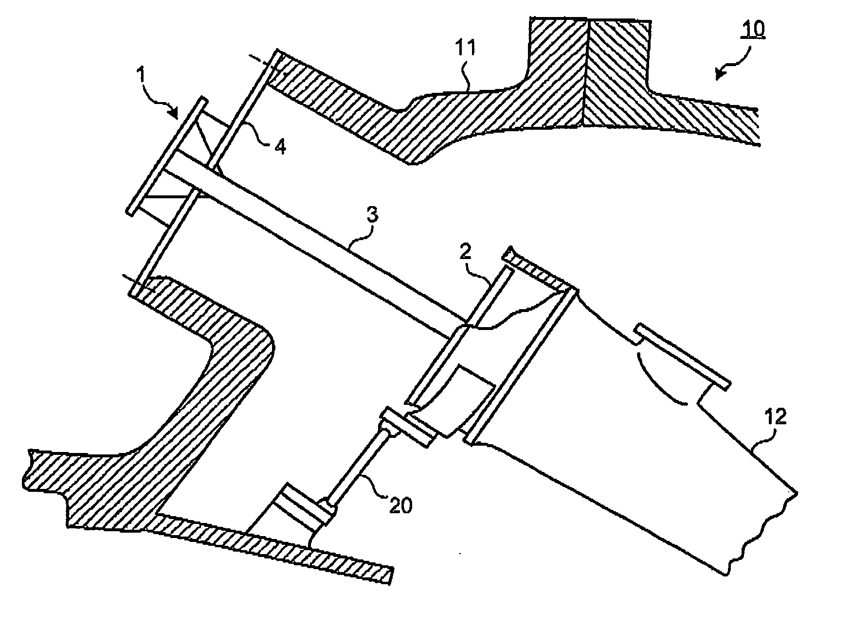
[0019]A combustor of a gas turbine includes an inner tube and a transition piece (not shown). The inner tube is installed in a chamber via an intermediate member of a so-called top hat. A fuel nozzle and a burner are inserted into the inner tube to be installed. The transition piece is installed in a rear stage of the inner tube, and is connected to a turbine vane array. In this combustor, a fuel injected from the fuel nozzle and compressed air supplied from a compressor is premixed in the inner tube to be ignited by the burner. The generated combustion gas is supplied to the turbine vane arrays through the transition piece.

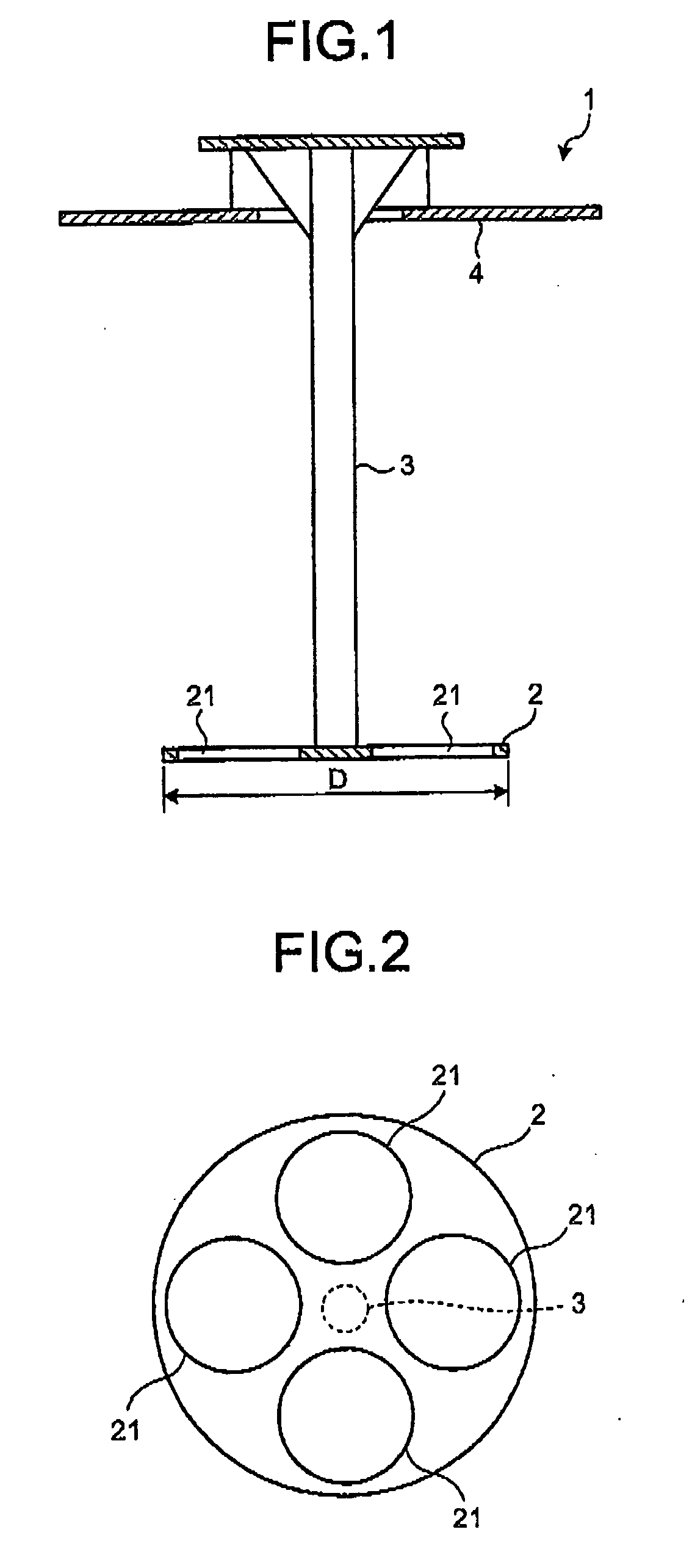
[0020]In an assembly process of the combustor, a jig 1 is used for positioning (aligning) the inner tube and the transition piece (see FIG. 1 and FIG. 2). The jig 1 includes an alignment member 2, a rod 3, and a support 4. The alignment member 2 has an outer circumferential shape which is substantially the same shape as an inner circumferential shape of an inlet ...


PUM

PropertyMeasurementUnit
Weightaaaaaaaaaa
Diameteraaaaaaaaaa
Shapeaaaaaaaaaa

Abstract

The jig 1 is used for positioning an inner tube and a transition piece of a combustor for a gas turbine when assembling the combustor. The jig 1 has the alignment member 2 that is inserted into the transition piece when positioning the transition piece to determine an installation position of the transition piece. The alignment member 2 has an outer circumferential shape which is substantially the same as an inner circumferential shape of the transition piece.

Description

BACKGROUND OF THE INVENTION[0001]1. Field of the Invention[0002]The present invention relates to a jig. More particularly, this invention relates to a jig that facilitates positioning work of a transition piece in an assembly process for a gas turbine combustor.[0003]2. Related Art Statement[0004]A jig for positioning (aligning) an inner tube and a transition piece is employed in an assembly process for a gas turbine combustor. A jig 100 of a related art includes a dial gauge 101, a rotary unit 102 to which the dial gauge 101 is installed, a rod 103 that is fixed to the rotary unit 102, and a support member 104 that supports the rod 103 (see FIG. 8).[0005]At the positioning work of the transition piece, the dial gauge 101 and the rotary unit 102 are inserted into an inlet portion of the transition piece that has been temporarily installed, and the support member 104 is installed in an installation spot (position for installing a top hat that retains an inner tube) of a chamber to fi...

Claims


Application Information

Patent Timeline
IPC IPC(8): B23Q3/00
CPCF01D25/285F01D9/023Y10T29/53909F05D2230/64
Inventor HORIUCHI, RYOSUKEBAIRAKU, SHOICHI
Owner MITSUBISHI POWER LTD
Why Eureka
Try Eureka