
Camera module

a technology of camera module and guide shaft, which is applied in the field of camera module, can solve the problems of difficult assembly and tilt of optical axis, and achieve the effect of minimizing assembly tolerance of guide shaft and high precision assembly

Inactive Publication Date: 2010-02-18
SAMSUNG ELECTRO MECHANICS CO LTD
View PDF5 Cites 21 Cited by
  • Summary
  • Abstract
  • Description
  • Claims
  • Application Information

AI Technical Summary

Benefits of technology

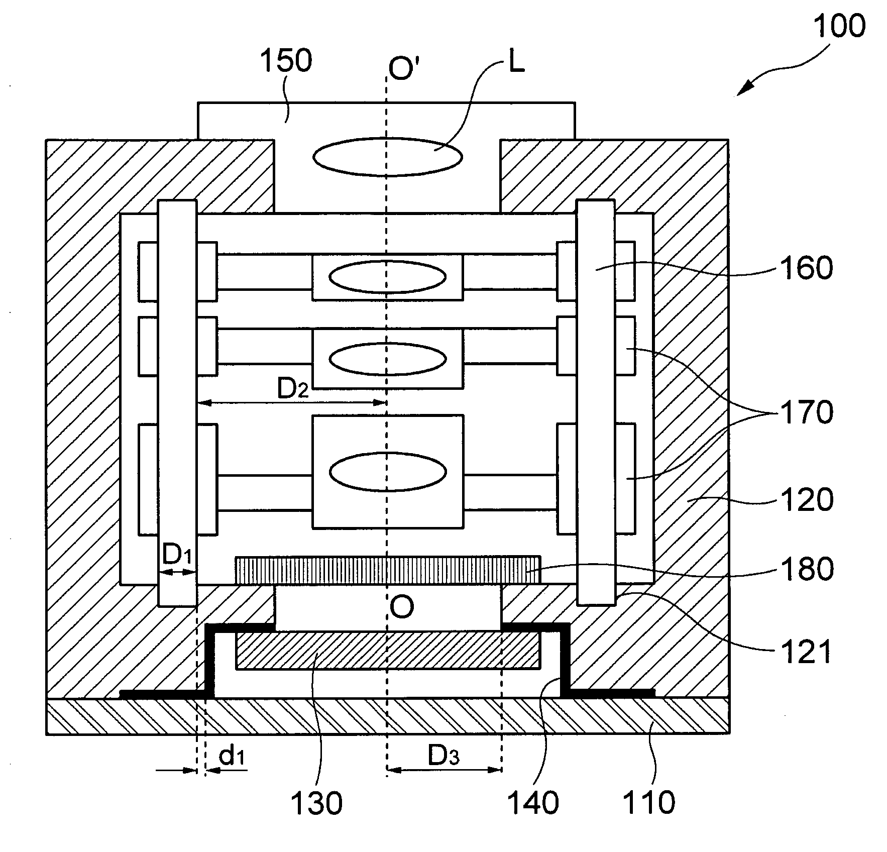
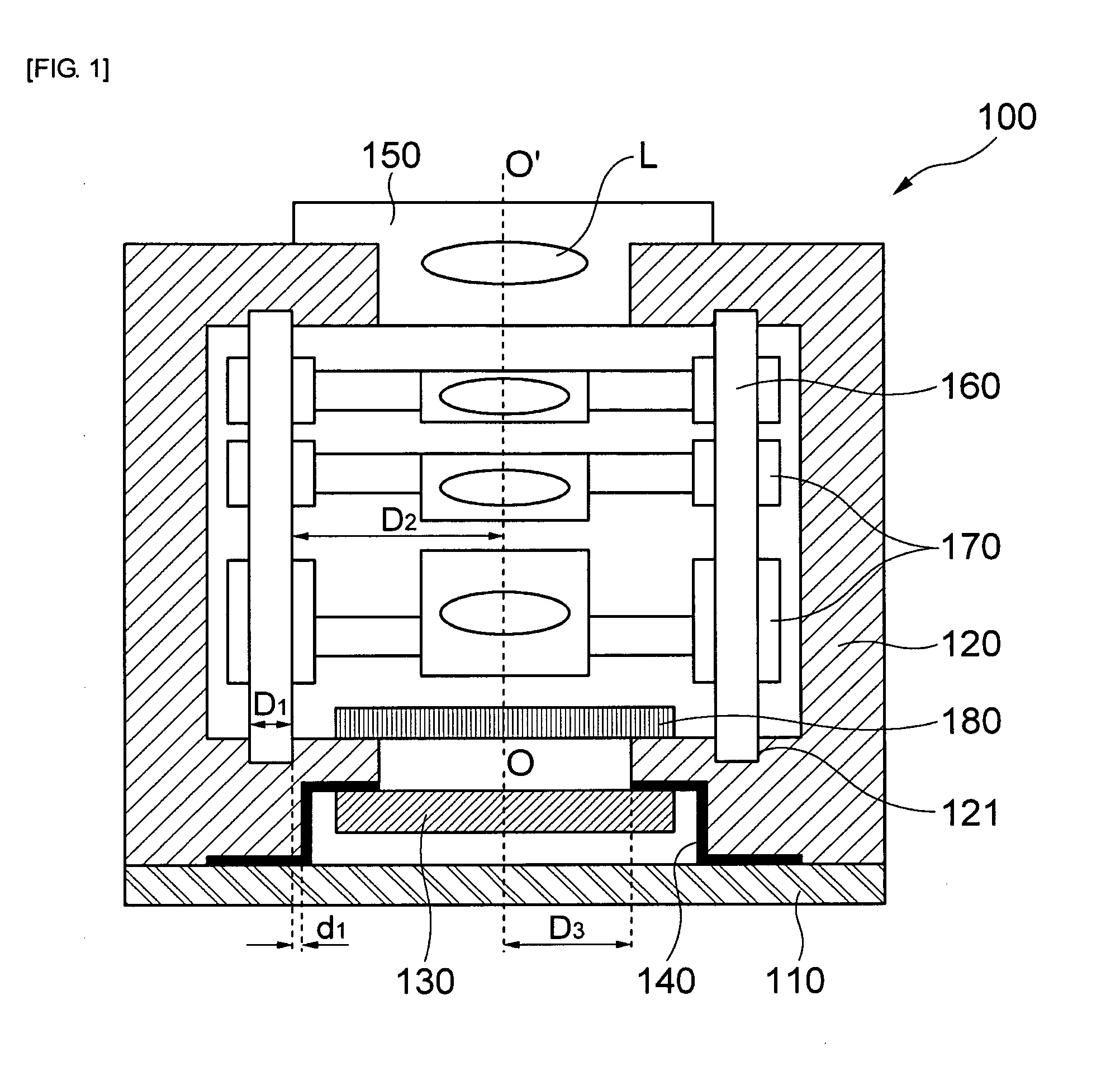
[0015]The present invention has been invented in order to overcome the above-described problems of the conventional camera module, it is, therefore, an object of the present invention to provide a camera module capable of minimizing an assembly tolerance between an image sensor and a lens by mounting the image sensor electrically connected through a conductive pattern to a lower part of a housing and minimizing a position tolerance of a guide shaft mounted in the housing and the conductive pattern.
[0022]In accordance with the present invention, the camera module is capable of implementing high precision assembly by being assembled to minimize assembly tolerances of the guide shafts and the image sensor with respect to the conductive pattern formed at the lower part of the housing when assembling the camera module by attaching the image sensor to the lower part of the housing including the lens driving module for auto-focusing or zoom adjustment inside and closely adhering the housing to the top surface of the substrate.

Problems solved by technology

However, because in the conventional camera module, the position of the housing coupled through the through hole of the substrate is determined and the position of the movable lens coupled inside the housing is determined with respect to the image sensor mounted through the wire bonding to the pads on the substrate, it is difficult to precisely assemble the camera module to match the optical axis between the image sensor and the lens and an increased assembly tolerance causes a tilt of the optical axis.

Method used


Image

  • Camera module
  • Camera module

Examples


Embodiment Construction

[0025]A matter regarding to an operation effect including a technical configuration to achieve the object of a camera module in accordance with the present invention will be clearly appreciated through the following detailed description with reference to the accompanying drawing illustrating preferable embodiment of the present invention.

[0026]First of all, FIG. 1 is a cross-sectional view showing a camera module in accordance with an embodiment of the present invention.

[0027]As shown in FIG. 1, in accordance with the embodiment of the present invention, a cameral module 100 includes a plate-shaped substrate 110, a housing 120 coupled to the substrate 110, conductive patterns 140 formed at a lower end portion of the housing 120 and an image sensor 130 coupled to a lower part of the housing 120 by being electrically connected through the conductive patterns 140.

[0028]The substrate 110 is a square plate-shaped printed circuit board or ceramic substrate and includes a plurality of pads...


PUM


Abstract

The present invention relates to a camera module including a substrate; a housing which is coupled to the substrate and includes a support unit extended to an inside of a lower part and a shaft insertion groove at one side of the support unit; a guide shaft vertically coupled inside the housing by inserting a lower end portion into the shaft insertion groove; a conductive pattern extended from a lower end portion of the housing to a bottom surface of the support unit; an image sensor closely coupled to the bottom surface of the support unit by being electrically connected to the conductive pattern; a lens barrel fixed to an upper part of the housing by coupling a lens inside; and a movable lens barrel vertically moved along the guide shaft by mounting lens inside.

Description

CROSS-REFERENCE TO RELATED APPLICATIONS[0001]This application claims the benefit of Korean Patent Application No. 10-2008-0079424 filed with the Korea Intellectual Property Office on Aug. 13, 2008, the disclosure of which is incorporated herein by reference.BACKGROUND OF THE INVENTION[0002]1. Field of the Invention[0003]The present invention relates to a camera module; and, more particularly, to a camera module capable of preventing a tilt of an optical axis between an image sensor and a lens by minimizing a position tolerance of a shaft insertion groove of a housing and a pattern formed at a lower end of the housing.[0004]2. Description of the Related Art[0005]In general, a CCM(Compact Cameral Module) is small and is applied to a diversity of IT(Information Technology) equipment including a potable mobile communication device such as a camera phone, a PDA (Personal Digital Assistant), and a smart phone and a toy camera and recently, the release of devices mounting small cameral mod...

Claims


Application Information

Patent Timeline
IPC IPC(8): H04N5/225
CPCH04N5/2257H04N5/2254H04N23/57H04N23/55H04N23/00
Inventor KIM, SO RIMLEE, DONG KYUN
Owner SAMSUNG ELECTRO MECHANICS CO LTD
Learn More