System debugging method, system debugging equipment, processor, wireless-communications interface IC and interface method thereof

a technology of contactless interface and system debugging method, which is applied in the field of system debugging equipment, wireless communication interface ic and interface method thereof, and close coupling contactless interface technology, can solve the problems of large antenna, large communication distance, and large antenna, so as to reduce the cost of a contactless interface

Inactive Publication Date: 2010-02-18
RENESAS ELECTRONICS CORP +1
View PDF15 Cites 17 Cited by
  • Summary
  • Abstract
  • Description
  • Claims
  • Application Information

AI Technical Summary

Benefits of technology

[0015]The following summarizes effects resulting from the representative aspects of the present invention disclosed in the specification.
[0016]It is possible to provide contactless interface for system debugging without the need for a large antenna or a large-scale circuit for modulation and demodulation.
[0017]It is possible to reduce costs for a contactless interface used for system debugging and the like.

Problems solved by technology

In many cases, however, the system debugging needs to ensure lower security than that for IC cards.
That is, a long communication distance consumes a large amount of power and requires a large antenna.
The need for a large antenna decreases the degree of freedom for mounting the antenna over a chip or a package.
The power consumption greatly increases.
The development cost also increases.
Further, it is difficult to change a wireless communication rate in accordance with internal states of the microcomputer.
It is difficult to accordingly decrease a carrier frequency for the wireless-communications interface.

Method used


Image

  • System debugging method, system debugging equipment, processor, wireless-communications interface IC and interface method thereof
  • System debugging method, system debugging equipment, processor, wireless-communications interface IC and interface method thereof
  • System debugging method, system debugging equipment, processor, wireless-communications interface IC and interface method thereof

Examples


Embodiment Construction

1. Representative Embodiments

[0068]The following describes overviews of representative embodiments disclosed in the present application. Parenthesized reference numerals in the drawings are contained in the overview of the representative embodiment and just exemplarily show instances contained in the concept of constituent elements assigned the reference numerals.

[0069] System Debugging Method

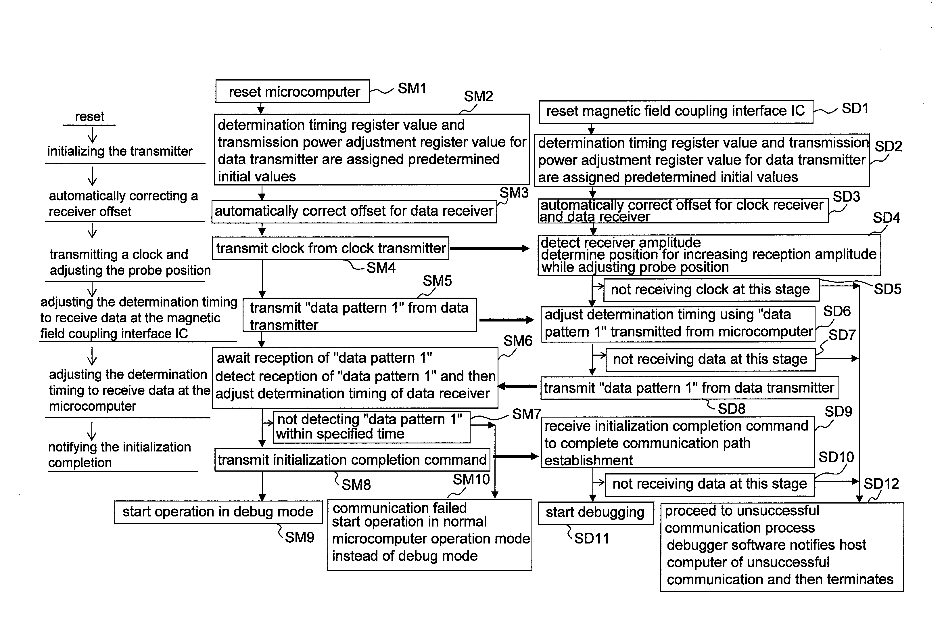
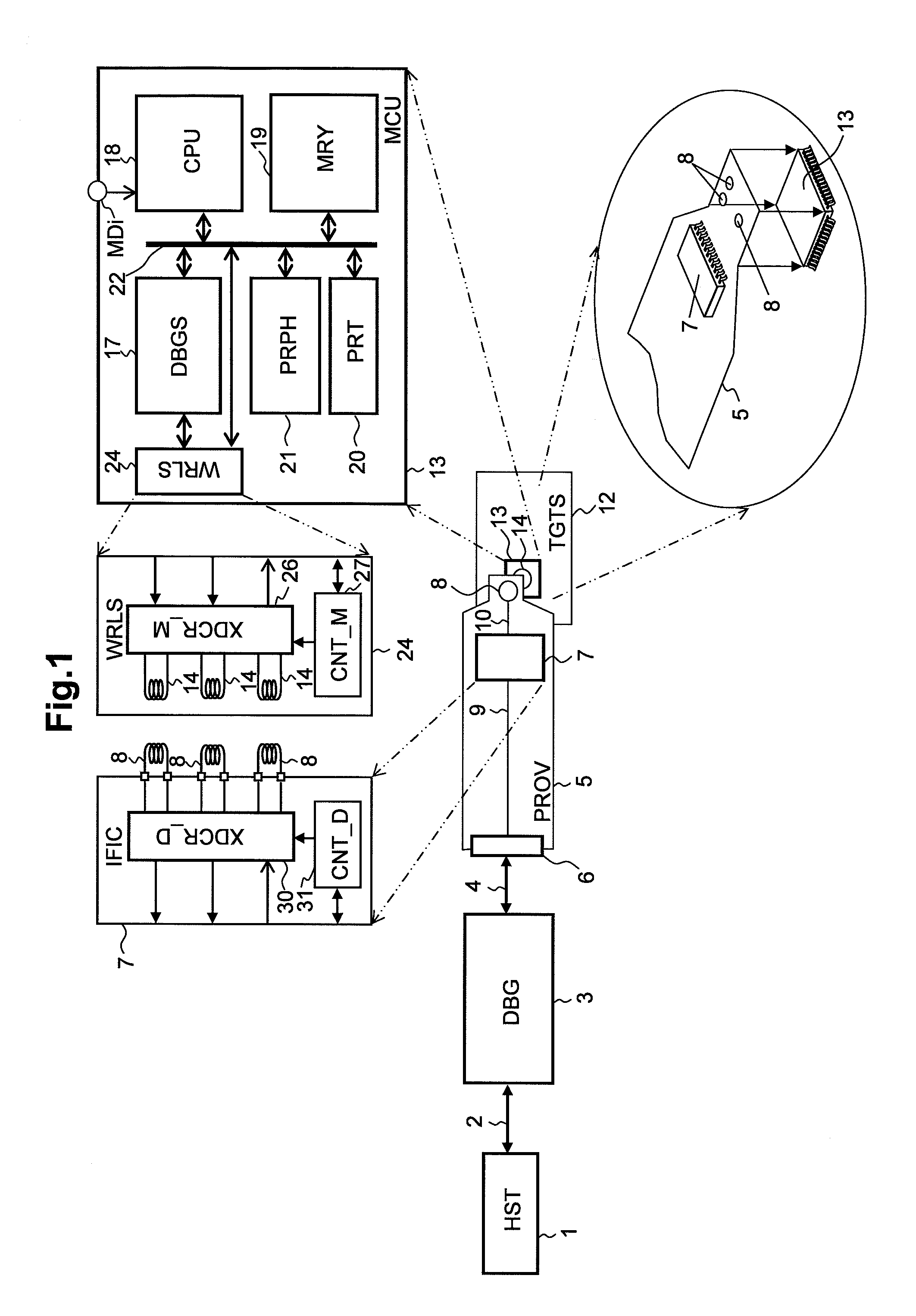
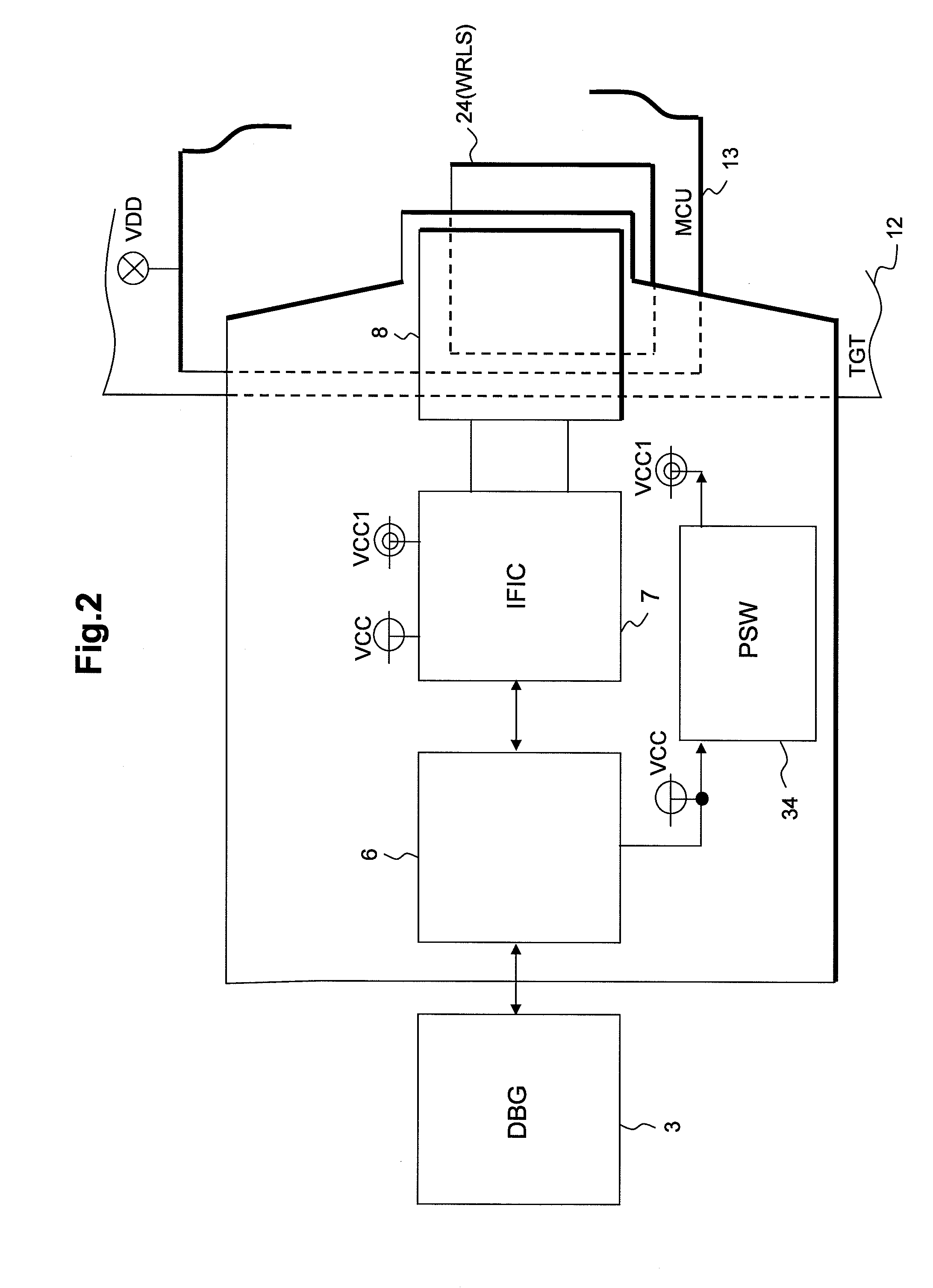
[0070]The system debugging method uses a debugger (3) to control a microcomputer (13) including a debugging support circuit (17) that supports the system debugging. The system debugging method performs wireless communication between the microcomputer and the debugger based on a pulse transmission technique using magnetic field coupling in which a first coil (14) provided for the microcomputer and a second coil (8) coupled with the debugger are placed opposite to each other. As an initial operation of the wireless communication, the microcomputer performs processes (SM2, SM3, and SM6) of configu...


PUM


Abstract

A pulse transmission technique is used for wireless communication between a microcomputer (13) having a debugging support circuit (17) and a debugger (13). The pulse transmission technique is based on magnetic field coupling between a first coil (14) provided for the microcomputer and a second coil (8) coupled with the debugger. During an initialization operation, the microcomputer performs a process of configuring a communication condition of the wireless communication to perform the wireless communication. The microcomputer awaits control from the debugger when the microcomputer establishes communication with the debugger. The debugger awaits establishment of the communication and proceeds to control of the microcomputer in accordance with the wireless communication. It is possible to provide contactless interface for system debugging without the need for a large antenna or a large-scale circuit for modulation and demodulation.

Description

TECHNICAL FIELD[0001]The present invention relates to an interface technology using magnetic field coupling of a coil and specifically to a close coupling contactless interface technology. For example, the invention relates to a technology effectively applicable to a system debugging that evaluates a target system using a debugger.BACKGROUND ART[0002]In addition to a wired communication interface using a cable, a wireless-communications interface using wireless communication is available as the technology of interfacing a debugger for system debugging with a target system. The technology described in Patent Document 1 uses wireless communication for interfacing an IC card reader to an interface cable having an antenna coil so as to debug a microcomputer for an IC card having a contactless interface. The technologies described in Patent Documents 2 and 3 provide a wireless-communications interface circuit for a target microcomputer coupled with a debugger and enable a system debuggin...

Claims


Application Information

Patent Timeline
Patent Type & Authority Applications(United States)
IPC IPC(8): H04B1/38G06F11/07H04L27/00
CPCG01R1/07G01R31/3025G01R31/31705H04W76/02H04W28/04H04W28/18G06F11/3656H04W76/10
Inventor IWATA, SHUNICHITAKAHATA, YOICHISUGAHARA, TOSHIHIKOTAKIKAWA, YUTAKASHIMIZU, YOSHIHIROISHIKURO, HIROKIKURODA, TADAHIRO
Owner RENESAS ELECTRONICS CORP
Why Eureka
Try Eureka