Keyboard and keys

a keyboard and key technology, applied in the field of keys, can solve the problems of large footprint, not all multi-function key designs provide prevention of sending an incorrect signal, single key does not provide multi-letter input, etc., to achieve the effect of maintaining the “feel” of the keyboard, avoiding lateral sliding and/or pushing of the keys, and rapid typing speed

Inactive Publication Date: 2010-02-18
HIRSCH
View PDF56 Cites 51 Cited by
  • Summary
  • Abstract
  • Description
  • Claims
  • Application Information

AI Technical Summary

Benefits of technology

[0014]Further, the disclosed keyboard duplicates the hand and finger positions, and also the finger movements, of a standard QWERTY keyboard, enabling a touch typist or a user familiar with a QWERTY keyboard to use this keyboard with no learning or retraining required.
[0015]Still further, by reducing a standard QWERTY keyboard to a single row of eight keys, the invention allows for true touch typing in small devices (such as a PDA or pocket dictionary), or in devices where space does not allow for anything but a very small keyboard, such as on the frame of a smart display or tablet personal computer.
[0016]The three-position and six-position key actuated switches of this invention duplicate the downward pressing motion of keys experienced with a standard typing keyboard. This is an important feature of the invention because it maintains the “feel” of a keyboard and avoids lateral sliding and/or pushing of the keys which are required in much of the prior art. Another important feature of Applicant's key actuated switches is that they have light actuation pressure which allows for fluid and continuous

Problems solved by technology

Stated another way, a single key does not provide for multi-letter input, such as two inputs for two different letters from a single key.
Keyboards with a fewer number of keys and a greater number of characters per key are known, but these keyboards do not use the standard QWERTY layout and require the operator to learn an entirely different system of typing.
Still further, in the prior art, not all multi-function key designs provide for prevention of sending an incorrect signal when a key is pressed improperly.
This may occur if a key is pressed improperly and there is closure of two sets of electrical cont

Method used


Image

  • Keyboard and keys
  • Keyboard and keys
  • Keyboard and keys

Examples


embodiment 1

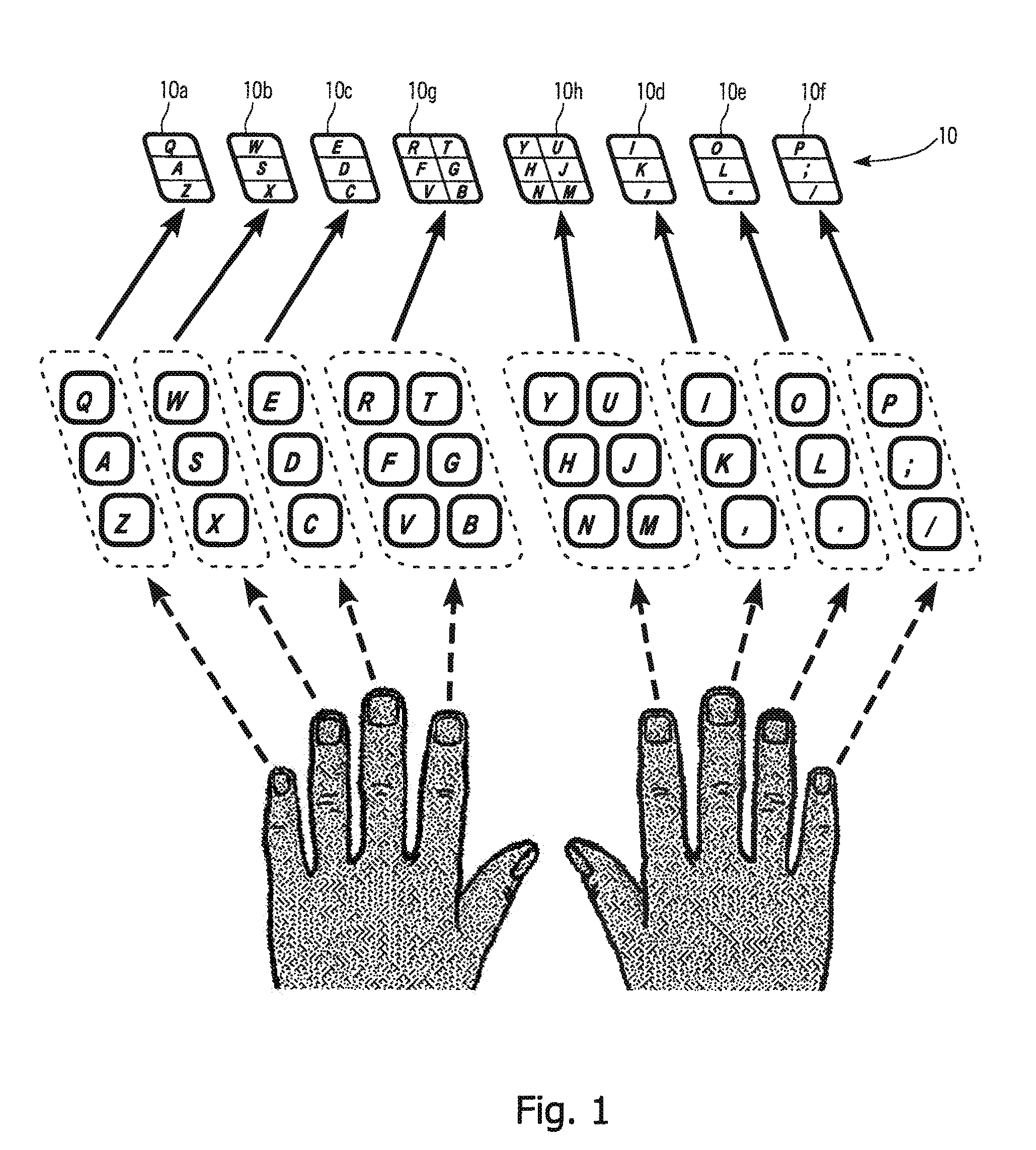
[0128]FIG. 9 shows a three-position key actuated switch of the type generally illustrated in FIG. 1 as keys 10a-10f. The key (90) is a key which may be used for the letters Q, A and Z. The key (90) has two groups of feet. There is a central group of four feet (91) which are all of the same length and which are longer than a second group of feet (92) which are located close to the top and the bottom edges of the key (90). FIG. 9a shows the positions of the feet beneath the key, and a side view when the key is not pressed down. FIG. 9b shows the key when pressed down at position A. In this position, the operative contact feet (91) are shown in black. Three of the four contact feet (91) are required to complete a circuit either by the conductive foot method or by closure of switches by the foot. When three of the four closures that are required for registering of the A keystroke occur, the letter A is signaled. In FIG. 9c there is shown the key when in a position where the letter Q is ...

embodiment 2

[0131]FIG. 11 shows another embodiment of a three-position key actuated switch. In this embodiment, there is a single conductive rubber foot with angled facets located on the underside of the key (111). The foot (112) has pivot edges (113) and (114) which allow the key to tilt or rock back and forth in response to pressure applied at different points. As shown in the side view of FIG. 11a, when no pressure is applied to the key, the key remains above a contact surface (115) located beneath it. On the other hand, when the key is pressed at a point for the letter A, the key moves straight down and closes contacts (116) located directly beneath this center section or facet of the key as illustrated in FIGS. 11d and 11b. When the key is pressed at a top portion, such as for the letter Q, the key will tilt about a pivot axis as shown in FIG. 11c, making contact at contact pair (117) when the upper facet moves downward.

embodiment 3

[0132]FIG. 15 shows another embodiment where a rocking type single foot is used, but the foot is nonconductive. This is shown in FIGS. 15a to 15d. Here the contacts lie beneath the facets of the key (155) and, as shown in FIG. 15b provide for closure at the center contact when the key is pressed straight down at a point for the letter A. This contact is illustrated in FIG. 15b and is identified as reference numeral (158). When the key is pressed at the letter Q the key will tilt about a pivot line (154) allowing closure at a contact (159) which is shown in FIG. 15c.


PUM


Abstract

In a preferred form, a keyboard has a single row of eight multi-position keys or groups of key elements with the letters arranged in a standard QWERTY keyboard configuration. The eight keys or key element groups correspond to the eight fingers used when touch typing; each finger operates one key, and that key contains all the letters that the finger normally accesses when touch typing on a standard QWERTY keyboard. With this design, no finger has to move to a different key or key element group while typing. In certain forms, when depressed at different locations on its key face, each key either moves straight down, or down while tilting slightly about one of a plurality of axes. Three-position keys have two tilt axes and six-position keys have five tilt axes. The switches utilize contacts located on the bottom of the switches which may be conductive or nonconductive.

Description

CROSS-REFERENCE TO RELATED APPLICATIONS[0001]This application claims benefit of U.S. Provisional Application No. 61 / 188,152, filed Aug. 7, 2008, and is a continuation-in-part of prior application Ser. No. 11 / 557,045, filed Nov. 6, 2006, which is a continuation-in-part of prior application Ser. No. 10 / 650,825, filed Aug. 29, 2003, which are hereby incorporated herein by reference in their entirety.FIELD OF THE INVENTION[0002]The present invention is directed to a keyboard which may be used for a full-size computer keyboard, a laptop, notebook or tablet computer keyboard, a personal digital assistant (PDA) device keyboard, a smart display keyboard, a pocket translator or dictionary keyboard, or other device which utilizes an alphanumerical keyboard. The keyboard comprises an input device for any data or any information desired for any type of keyboard-compatible device. The keyboard more specifically relates to the standard QWERTY keyboard configuration which is most often used in tou...

Claims


Application Information

Patent Timeline
IPC IPC(8): B41J5/00
CPCB41J5/10H03M11/06G06F3/0219G06F3/0234G06F3/04886G06F2203/04809H01H13/705H01H13/84H01H2217/004H01H2217/024H01H2217/036H01H2221/002H01H2221/008H01H2221/012G06F3/0202
Inventor HIRSCH, STEVEN B.
Owner HIRSCH
Why Eureka
Try Eureka