Deep Hole Cutting Apparatus

Inactive Publication Date: 2010-02-18
YUNITAKKU
View PDF5 Cites 14 Cited by
  • Summary
  • Abstract
  • Description
  • Claims
  • Application Information

AI Technical Summary

Benefits of technology

[0012]According to the deep hole cutting apparatus in accordance with the first aspect of the present invention, the guide pad brazed on the outer periphery of the cutting head portion is slantingly arranged in such a manner that the tool distal end side thereof is further forward in the tool rotational direction than the rear end side thereof. As a result, an abraded area is not biased on the outer surface of the guide pad even if an abrasion center on the surface of the guide pad is shifted further backward in the tool rotational direction apart from the tool distal end. The guide pad as a whole equally press contacts with inner circumferential surface of the cutting hole, whereupon stress by the pressed contact is turned toward the tool center. This leads to stabilization of cutting states and an

Problems solved by technology

This results in destabilizing a cutting state and reducing working accuracy.
Furth

Method used


Image

  • Deep Hole Cutting Apparatus
  • Deep Hole Cutting Apparatus
  • Deep Hole Cutting Apparatus

Examples


Example

[0022]1A Drill head[0023]10a Cutting head portion[0024]18 Pad mounting depression[0025]2A to 2C Cutting blades[0026]5 Guide pad[0027]5a Circular arc-shaped surface[0028]50 Raw material tip for guide pad[0029]H Cutting hole[0030]L0 Tool axis direction[0031]L2 Bisector in width direction[0032]S Cutting circle[0033]y Tool rotational direction[0034]θ Angle

DETAILED DESCRIPTION

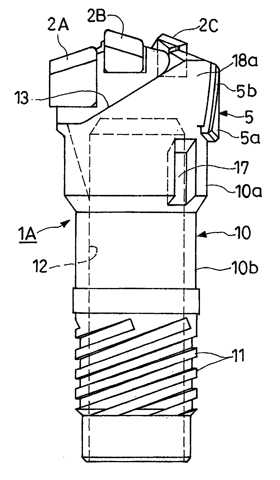
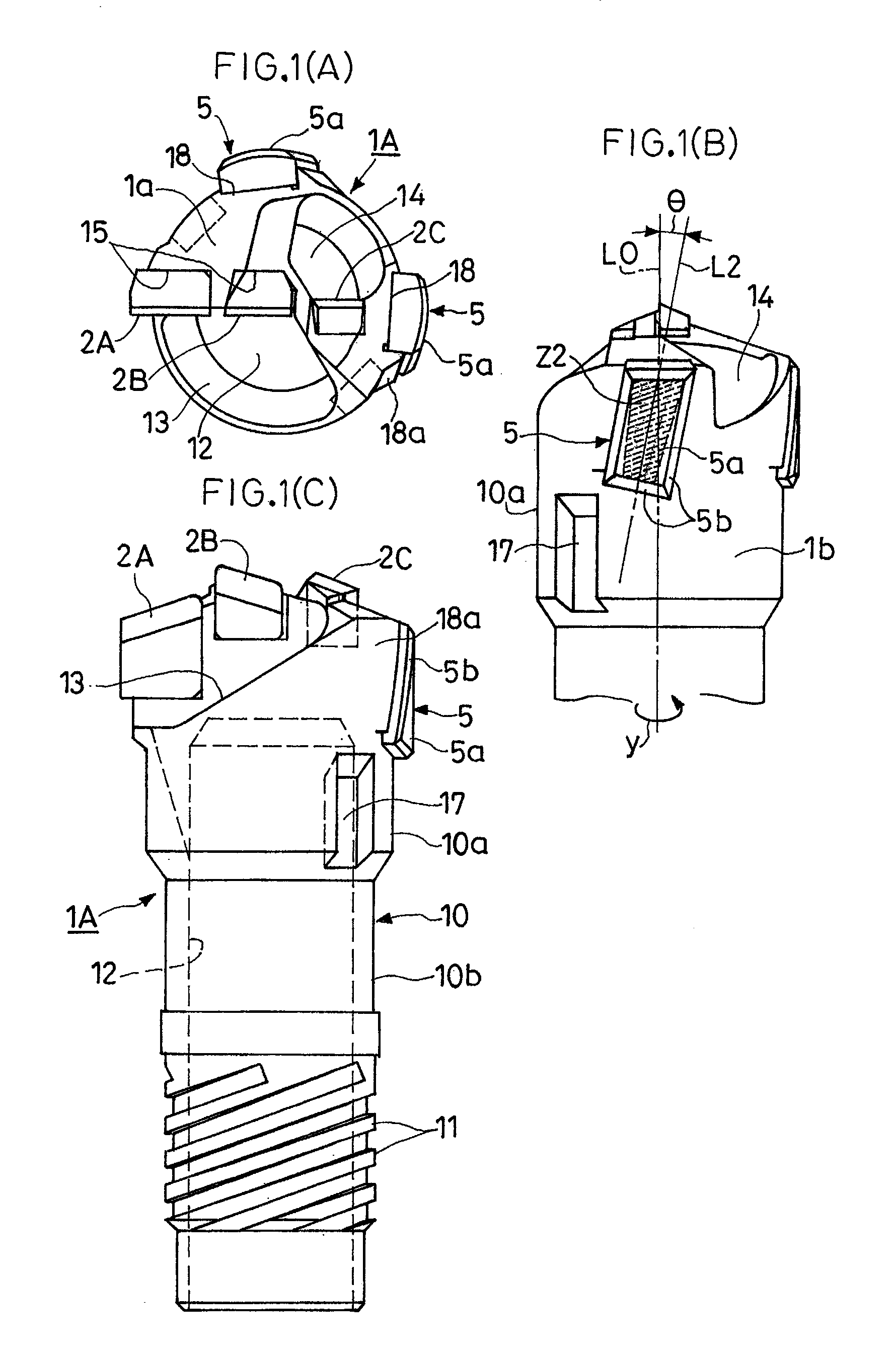
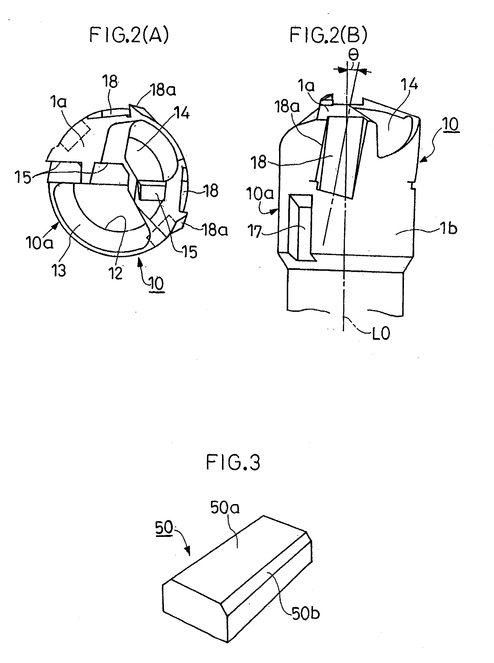
[0035]Hereinafter, an embodiment of a deep hole cutting apparatus in accordance with the present invention is described in detail with reference to the drawings. FIGS. 1A to 1C illustrate a drill head 1A in the deep hole cutting apparatus of the embodiment. FIGS. 2A to 2B illustrate a head body 10 of the drill head 1A. FIG. 3 illustrates a raw material tip 50 for a guide pad used in the drill head 1A. FIGS. 4A to 4B illustrate the raw material tip 50 in a brazed state on the head body 10. FIG. 5 illustrates a main part on a distal end surface of the drill head 1A after the raw material tip 50 is ground. In the deep...


PUM

PropertyMeasurementUnit
Angleaaaaaaaaaa
Circumferenceaaaaaaaaaa

Abstract

A deep hole cutting apparatus has a guide pad brazed to a cutting head section. With the deep hole cutting apparatus, high machining accuracy can be obtained in a stable cutting status and the service life of the guide pad is lengthened. A guide pad (5) brazed to a cutting head section (10a) is diagonally arranged so that the leading end side of the tool is closer to the front side in a tool rotating direction (y) compared with the rear end side of the tool.

Description

FIELD OF THE INVENTION [0001]The present invention relates to a cutting apparatus used for deep-hole drilling work, and in particular, a deep hole cutting apparatus brazed with a guide pad on an outer periphery of a cutting head portion.BACKGROUND [0002]A guide pad provided on an outer periphery of a cutting head portion in a deep hole cutting apparatus, in general, slidingly contacts with an inner circumference of a cutting hole during drilling, rendering an inner circumferential surface of the cutting hole receiving a cutting reaction force by a cutting blade. By a so-called burnishing action of keeping a physical relationship between the slidingly contacted area and the cutting blade constant all the time, the cutting head portion is maintained in a rotational state on a constant axis line without runout, thereby enhancing cutting accuracy. The guide pad also exhibits an action of crushing and smoothing unevenness on the inner circumference of the hole involved in cutting. A guid...

Claims


Application Information

Patent Timeline
IPC IPC(8): B23B51/00B23B41/02
CPCB23B51/0493Y10T408/5586B23B2251/56B23B2240/08B23B27/16B23B51/00B23B51/02B23B51/06
Inventor NOMURA, TAKUJISAKAI, MAKATO
Owner YUNITAKKU
Why Eureka
Try Eureka