Hinged Partition and Arrangement for Closing Off a Room Against a Fluid Flowing into the Room or Out of the Room

a technology for closing off a room and a fluid, applied in the direction of hinges, door/window fittings, building components, etc., can solve the problems of inability to ensure sealing function or insufficiently reduced extent, expensive alignment of the axis or etc., to achieve the effect of reducing the total weight of the hinged partition, reducing the thickness of the barrier, and increasing the lifting for

Inactive Publication Date: 2010-02-25
HELMUT ANHAMM
View PDF5 Cites 8 Cited by
  • Summary
  • Abstract
  • Description
  • Claims
  • Application Information

AI Technical Summary

Benefits of technology

[0038]It is especially advantageous when the cross-section of the hinged partition is essentially wedge-shaped. In this way, a defined position of the hinged partition in a fluid is also achieved. The thickness of the hinged partition preferably decreases in the direction of the rotary axis. Moreover, the wedge-shaped design of the hinged partition has the advantage that the total weight of the hinged partition will be reduced. The reduction of the thickness of the barrier in the direction of the rotary axis has the advantage that the center of gravity and the midpoint of the lifting force are removed further from the pivot point. In this way better self-adjustment of the floating height is achieved, since the partition, when this is immersed further into the liquid, experiences a greater increase in the lifting force than when the barrier is designed to have a constant thickness. Similarly, when the partition rises further out of the fluid, a larger decrease of the volume available for buoyancy is achieved. Moreover, the incorporation of the hinged partition or of the arrangement is simplified with the aid of a pouring method, especially a concrete pouring method. As a result of the essentially wedge-shaped design of the hinged partition, essentially no air can collect under the hinged partition, which leads to the fact that the hinged partition will not be flooded underneath correctly, as a result of which the trough will not be attached correctly. This can lead to a bowing upward of the trough in which the hinged partition is arranged at these locations, and therefore the hinged partition will be pivoted away from the actually intended position and thus will no longer lie flat on the bottom. For example, if a vehicle drives over the hinged partition then the areas that are bowed upward will undergo a greater load, which may lead to a stress of the hinged partition since additional shifting of the load does not occur.
[0039]If springs are used for moving the hinged partition, then it is especially advantageous for the springs to be chosen so that the hinged partition can be pivoted manually with a small manual force over the entire pivoting range. This simplifies the cleaning and manual checking of the functioning of the hinged partition. Moreover, the danger of injury to the operator is highly reduced in this way. It is of especially great advantage when the spring force is adjusted so that the hinged partition after manual operation will be stopped automatically in the vertical position. In this way the cleaning of the barrier is simplified even further.

Problems solved by technology

Moreover, especially in the case of hazardous material storage, there is a necessity to close off the storage against the exit of fluids into the surroundings.
The problem in such a device is that, due to the manufacturing tolerances, an expensive alignment of the axis or of the hinged partition is necessary in order to ensure that the sealing function will be reached to a sufficient extent.
Due to the large evolution of heat that occurs during fires, the problem arises that the components of the device behave differently thermally and the sealing function cannot be assured or can be assured only to a reduced extent.

Method used


Image

  • Hinged Partition and Arrangement for Closing Off a Room Against a Fluid Flowing into the Room or Out of the Room
  • Hinged Partition and Arrangement for Closing Off a Room Against a Fluid Flowing into the Room or Out of the Room
  • Hinged Partition and Arrangement for Closing Off a Room Against a Fluid Flowing into the Room or Out of the Room

Examples


Embodiment Construction

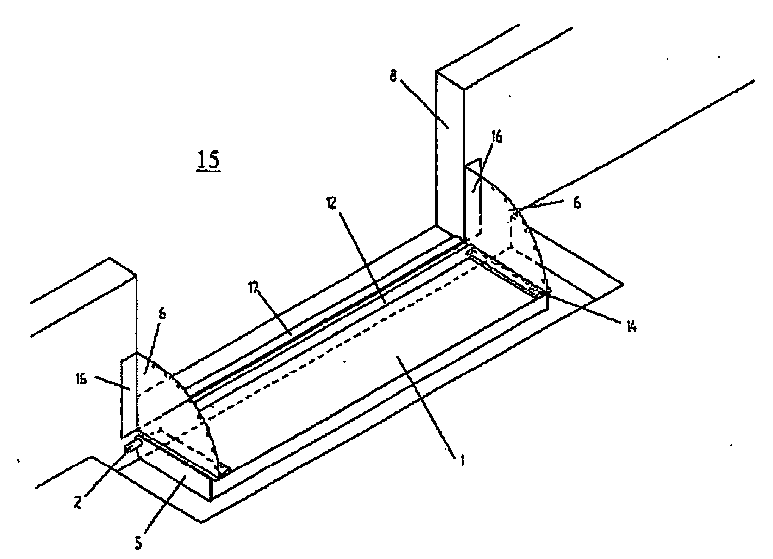
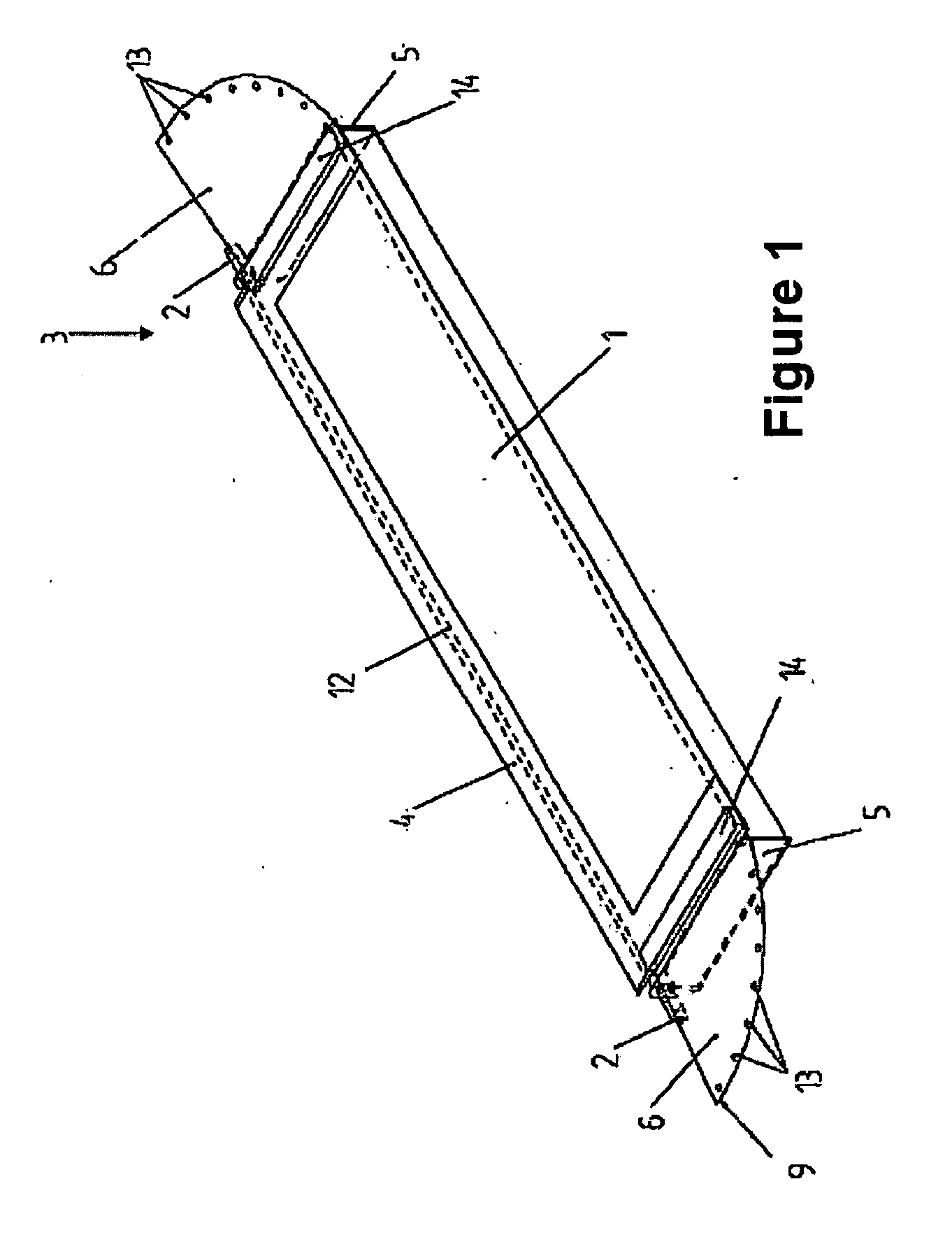
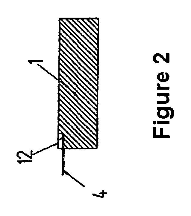
[0058]FIG. 1 shows a perspective view of a practical example of a hinged partition 1 of an arrangement for closing off a room against a fluid flowing into the room or out from the room, especially a combustible fluid. The hinged partition 1 is formed by a prismatic body in this representation, which can be sunk into a recess of a floor, the recess not being shown. The hinged partition 1 can be pivoted around an axis 2 from a first position into a second position. For example, the hinged partition 1 can have a metallic surface. It can be formed by a box made of metal in which a core is arranged that can be, for example, made of a plastic or similar material. A flame-retardant layer may be arranged between the core and the outer mantle.

[0059]In the practical example shown, the hinged partition 1 is connected to a seal 3. The seal 3 can be made of one or several parts. The seal 3 is designed in a sheet-like manner. Preferably it is made of polytetrafluoroethylene.

[0060]Next to the axis...


PUM


Abstract

An arrangement which has a hinged partition is proposed in order to close off a room against a fluid, in particular a flammable liquid, flowing into the room or out of the room. The hinged partition can be pivoted about an axis from a first position into a second position. A seal of sheet-like formation is connected to the hinged partition and a frame. At least one screening means is provided in the side regions of the seal and of the hinged partition, this screening means protecting the seal against increased levels of heat.

Description

FIELD AND BACKGROUND OF THE INVENTION[0001]The object of the invention refers to an arrangement for closing off a room against a fluid flowing into the room or out from the room, especially a combustible fluid.[0002]It is known that doors or passageways of a room, especially of a workshop or of a storage room can be closed off by partitions. A hinged partition is to ensure that a fluid cannot leave a room or enter into this room. The fluids can be water, chemicals, oils or their mixtures. Such fluids or fluid mixtures occur especially when water used for fire extinguishing by the fire department or by a sprinkling installation is pumped into the room. Moreover, especially in the case of hazardous material storage, there is a necessity to close off the storage against the exit of fluids into the surroundings.[0003]A room is defined not only as a building or a part of a building, such as, for example an underground parking structure, a workshop, a storage room, etc., but also areas de...

Claims


Application Information

Patent Timeline
Patent Type & Authority Applications(United States)
IPC IPC(8): E06B7/16E05C19/00
CPCA62C2/06E06B2009/007E06B9/04Y10T292/08
Inventor ANHAMM, DAG
Owner HELMUT ANHAMM
Why Eureka
Try Eureka