
Insulated log homes

Inactive Publication Date: 2010-02-25
WRIGHTMAN RONALD A
View PDF19 Cites 14 Cited by
  • Summary
  • Abstract
  • Description
  • Claims
  • Application Information

AI Technical Summary

Benefits of technology

[0003]It is well known to utilize logs stacked one above another to form the wall of a house. The intersection of logs at corners is accommodated through overlapping joints, either a saddle splined joint or a dovetail joint by providing a connection to a post. Such construction provides an aesthetically pleasing finished product and reflects the traditional values of the environment in which such houses are typically built. Such houses are formed from logs that are rough hewn to shape as they are built into a wall and the gap between the logs sealed with “chinking”. As an alternative to the hand hewn log homes, machined logs have been utilized in the construction. Machined logs have a uniform cross section and the abutting faces of the logs are machined to form a seal system to inhibit the ingress of air between the logs making up the wall. Such construction offers greater thermal efficiency for the building and assists in meeting the air infiltration standards of the relevant building codes.
[0011]There is therefore the need for a log construction in which the thermal rating of the log may be increased without destroying the structural integrity of the log.

Problems solved by technology

Logs of this dimension are expensive and difficult to obtain in volume and as such make it difficult to attain the minimum values required.
It is of course possible to increase the thermal efficiency by insulating the internal surface of the wall but this detracts from the inherent aesthetic value of the log wall construction.
However such an arrangement destroys the integrity of the log and requires careful manufacture in order to ensure that the natural movement of the wood does not result in degradation of the log itself.
Moreover, such an arrangement also makes it difficult for the inter-engaging seal profiles to be manufactured and maintained.
Because of the natural movement of the material of the log, an effective seal can only be obtained if the two logs are forced into contact and subsequently held with the seal in a compressed state.
The tapered profile of the sealing area therefore generates a significant lateral load when the logs are assembled in to a wall that must be resisted if the seal is to remain effective and ingress of air is to be avoided.
A log formed by a series of laminar sections does not have the necessary lateral strength to resist the lateral loads imposed and would therefore not offer a practical solution.

Method used


Image

  • Insulated log homes
  • Insulated log homes
  • Insulated log homes

Examples


Embodiment Construction

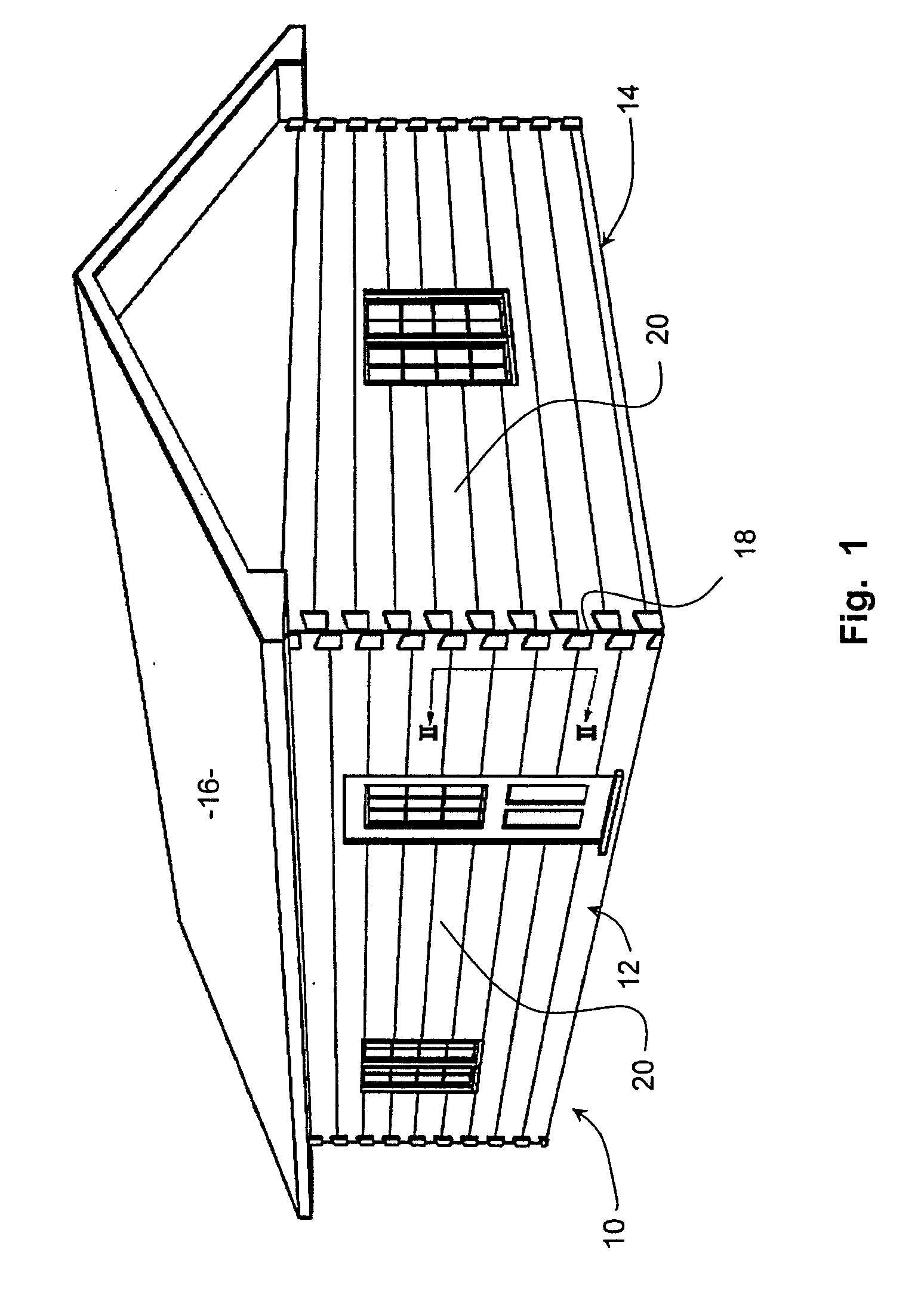
[0033]Referring therefore to the drawings, in FIG. 1 a house 10 has side walls 12, 14 that support a roof 16. The side walls 12, 14 intersect at a corner 18.

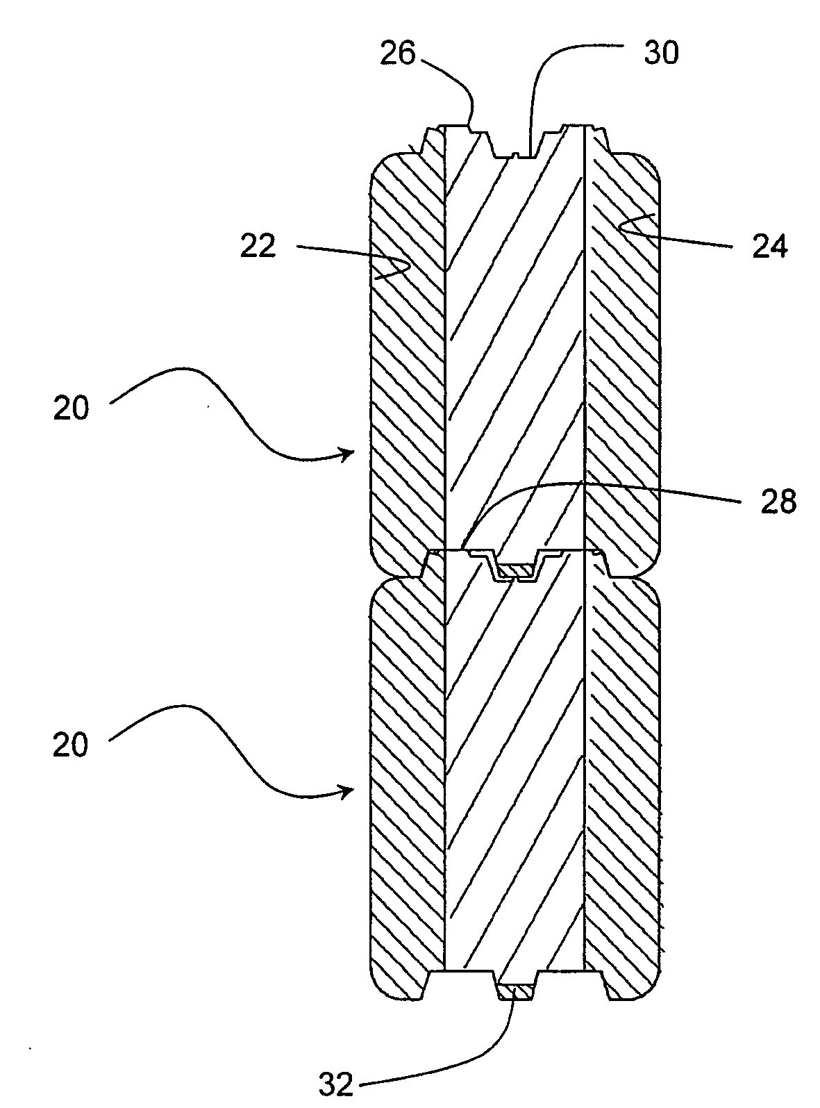
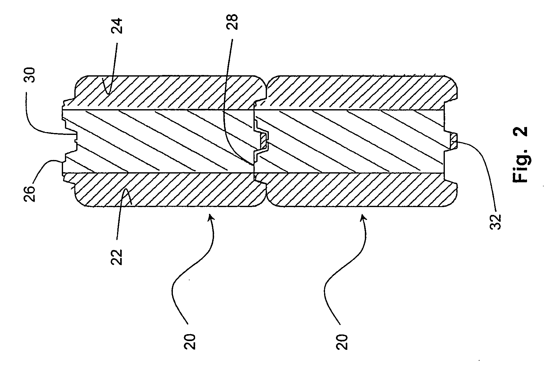
[0034]Each of the walls 12, 14 is formed from a plurality of logs 20 that extend horizontally and are stacked one above another in a vertical direction. As can be seen in FIG. 2, the logs 20 have a pair of oppositely directed surfaces, designated an outer surface 22 and an inner surface 24. The outer surface 22 and inner surface 24 are interconnected by an upwardly directed surface 26 and a downwardly directed surface 28, it being understood that the terms upper and lower refers to the normal orientation of the logs 20 when assembled into a wall 12,14. The upper and lower surfaces 26, 28 are milled to have complimentary profiles 30,32 such that when stacked one above the other, the profile 32 of lower surface 28 is snugly received on the profile 30 of the upper surface 26. Seals may be incorporated between the tongue and groove ...


PUM

PropertyMeasurementUnit
Fractionaaaaaaaaaa
Fractionaaaaaaaaaa
Fractionaaaaaaaaaa

Abstract

A log for a log home has a plurality of pockets formed within the body of the log. The pockets are filled with foam to enhance the thermal rating of the log.

Description

CROSS-REFERENCE TO RELATED APPLICATIONS[0001]This application claims priority from Canadian Patent Application No. 2,633,134 filed on Jun. 25, 2008 and U.S. Provisional Patent Application No. 61 / 090,757 filed on Aug. 21, 2008 all of which are incorporated by reference.FIELD OF THE INVENTION[0002]The present invention relates to logs for use in log homes.SUMMARY OF THE INVENTION[0003]It is well known to utilize logs stacked one above another to form the wall of a house. The intersection of logs at corners is accommodated through overlapping joints, either a saddle splined joint or a dovetail joint by providing a connection to a post. Such construction provides an aesthetically pleasing finished product and reflects the traditional values of the environment in which such houses are typically built. Such houses are formed from logs that are rough hewn to shape as they are built into a wall and the gap between the logs sealed with “chinking”. As an alternative to the hand hewn log homes...

Claims


Application Information

Patent Timeline
IPC IPC(8): E04C3/29B05D3/00B29C65/00
CPCE04C3/29E04B2/702
Inventor WRIGHTMAN, RONALD A.
Owner WRIGHTMAN RONALD A
Learn More